Deploy Binaries
The following binaries are used for the Network boot mode:
bl2_bp_spi-smarc-rzg3e.srec: Bootloader for SPI memory that initializes the hardware components needed to run U-Boot.fip-smarc-rzg3e.srec: Firmware package that bundles U-Boot and other secure components into one boot image.Flash_Writer_SCIF_RZG3E_EVK_LPDDR4X.mot: Software that is loaded into the RZ/G3Es RAM to write bootloader files into flash memory.
core-image-minimal-smarc-rzg3e.rootfs.tar.gz: Compressed Linux disk image containing the rootfs (Linux kernel, drivers, applications and system configurations).
core-image-weston-smarc-rzg3e.rootfs.tar.gz: Compressed Linux disk image containing the rootfs (Linux kernel, drivers, applications and system configurations).
By using the Network boot mode, the bootloaders need to be manually flashed to the board.
Prepare Linux Host PC
-
Copy
rzg3e-ethosu-v3.0_Prebuilt_Binaries.zipfile to Linux Host PC. -
Extract the zip file.
-
Copy
core-image-weston-smarc-rzg3e.rootfs.tar.gzfile to a new directory in the TFTP/NFS directory. -
Navigate to TFTP/NFS directory and extract the tarball.
-
Copy
core-image-minimal-smarc-rzg3e.rootfs.tar.gzfile underbuild/tmp/deploy/images/smarc-rzg3e/to a new directory in the TFTP/NFS directory. -
Navigate to TFTP/NFS directory and extract the tarball.
Prepare Bootloaders
- Copy bootloader files under
build/tmp/deploy/images/smarc-rzg3eto the directory used for loading bootloader files.bl2_bp_spi-smarc-rzg3e.srecfip-smarc-rzg3e.srecFlash_Writer_SCIF_RZG3E_EVK_LPDDR4X.mot
- Copy bootloader files under
build/tmp/deploy/images/smarc-rzg3eon Linux Host PC to Windows PC.bl2_bp_spi-smarc-rzg3e.srecfip-smarc-rzg3e.srecFlash_Writer_SCIF_RZG3E_EVK_LPDDR4X.mot
Write Bootloaders to SPI Flash
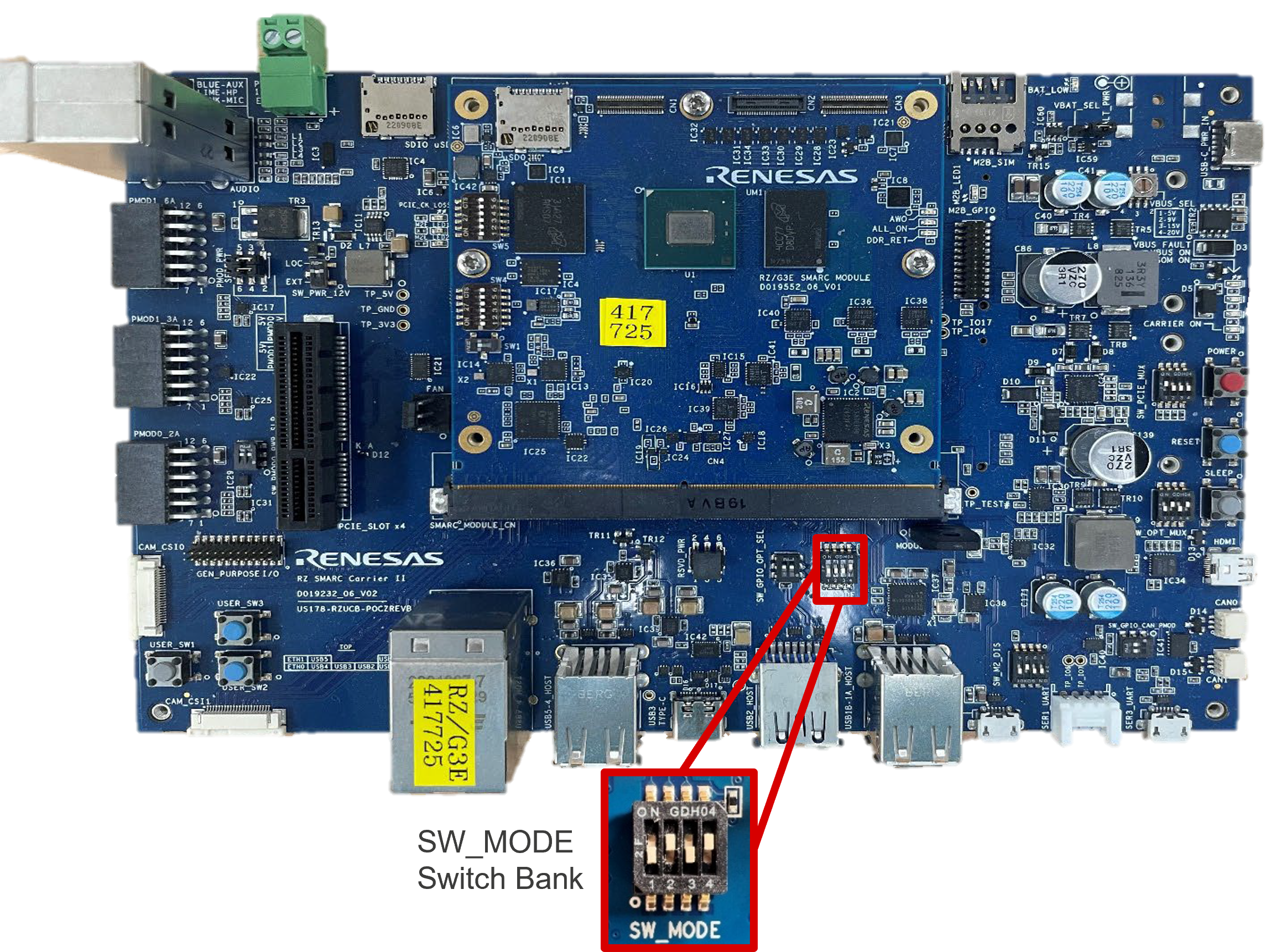
-
Set
SW_MODEswitch bank on the SMARC Carrier Board to SCIF Download Mode.Switch Bank SW1 SW2 SW3 SW4 SW_MODE OFF ON OFF ON -
Start up a serial terminal connection (e.g. TeraTerm or Minicom) on Host PC, making sure the correct COM port and settings are used.
Variable Value Baud rate 115200bpsData 8 bitParity noneStop 1 bitFlow control none -
Power ON the board by pressing the POWER button for at least 1 second until the CARRIER ON LED lights up.
The CARRIER ON LED is located above the POWER button.-
The following message should be printed to console.
-
-
Send the
Flash_Writer_SCIF_RZG3E_EVK_LPDDR4X.motfile. If successful, the serial console should print the product code. -
Write BL2 Loader to memory.
>xls2 ===== Qspi writing of RZ/G3S Board Command ============= Load Program to Spiflash Writes to any of SPI address. Dialog : AT25QL128A Program Top Address & Qspi Save Address ===== Please Input Program Top Address ============ Please Input : H'8003600 ===== Please Input Qspi Save Address === Please Input : H'0 please send ! ('.' & CR stop load) Erase SPI Flash memory... Erase Completed Write to SPI Flash memory. ======= Qspi Save Information ================= SpiFlashMemory Stat Address : H'00000000 SpiFlashMemory End Address : H'00032D6F =========================================================== -
Send the
bl2_bp_spi-smarc-rzg3e.srecfile. -
Write FIP Loader to memory.
>xls2 ===== Qspi writing of RZ/G3S Board Command ============= Load Program to Spiflash Writes to any of SPI address. Dialog : AT25QL128A Program Top Address & Qspi Save Address ===== Please Input Program Top Address ============ Please Input : H'0 ===== Please Input Qspi Save Address === Please Input : H'60000 please send ! ('.' & CR stop load) Erase SPI Flash memory... Erase Completed Write to SPI Flash memory. ======= Qspi Save Information ================= SpiFlashMemory Stat Address : H'00060000 SpiFlashMemory End Address : H'00115CBE =========================================================== -
Send the
fip-smarc-rzg3e.srecfile. -
Power OFF the board by pressing the POWER button for at least 1 second until the CARRIER ON LED turns off.
The CARRIER ON LED is located above the POWER button.
Boot Procedure
Switch Settings

Set SW_MODE switch bank on the SMARC Carrier Board for QSPI Boot.
| Switch Bank | SW1 | SW2 | SW3 | SW4 |
|---|---|---|---|---|
| SW_MODE | OFF | OFF | OFF | ON |
Setup U-Boot Environment
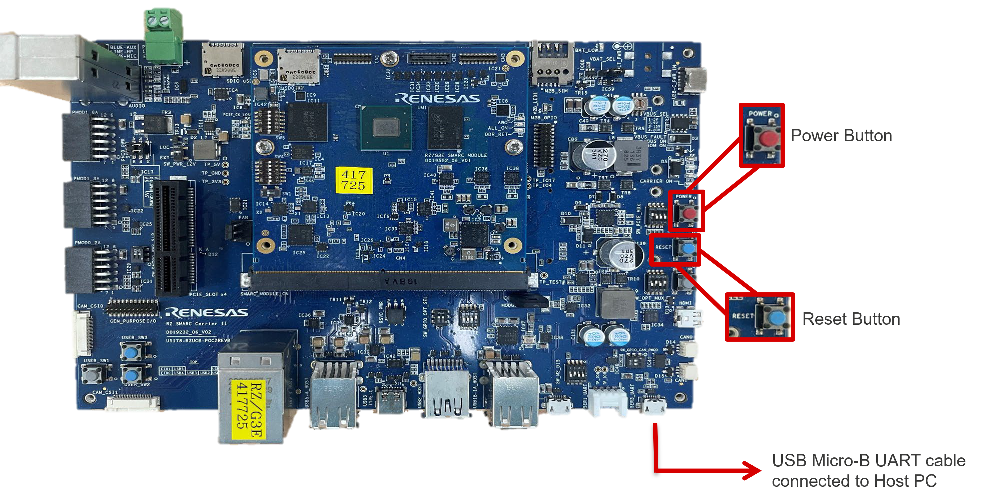
-
Start up a serial terminal connection (e.g. TeraTerm or Minicom) on Host PC, making sure the correct COM port and settings are used.
Variable Value Baud rate 115200bpsData 8 bitParity noneStop 1 bitFlow control none -
Power ON the board by pressing the POWER button for at least 1 second until the CARRIER ON LED lights up.
The CARRIER ON LED is located above the POWER button. -
Press any key to stop the autoboot within 3 seconds of U-Boot starting.
If U-Boot attempts to boot, press the RESET button and try again. -
Set up the U-Boot environment.
env default -a
setenv ipaddr '192.168.1.2'
setenv serverip '192.168.1.1'
setenv ethaddr '00:11:22:33:44:55'
setenv bootcmd 'tftp 0x48080000 rzg3e/boot/Image; tftp 0x48000000 rzg3e/boot/r9a09g047e57-smarc.dtb; booti 0x48080000 - 0x48000000'
setenv bootargs 'console=ttySC0,115200 debug rootwait root=/dev/nfs rw nfsroot=192.168.1.1:/tftpboot/rzg3e,v3 ip=192.168.1.2:::::eth0:off'
saveenv
Note
The IP/MAC addresses should be set up according to the Linux Host PCs environment.
-
Power OFF the board by pressing the POWER button for at least 1 second until the CARRIER ON LED turns off.
The CARRIER ON LED is located above the POWER button.
Boot The Board
-
Whilst the board is not powered, confirm that following hardware configuration is being used.
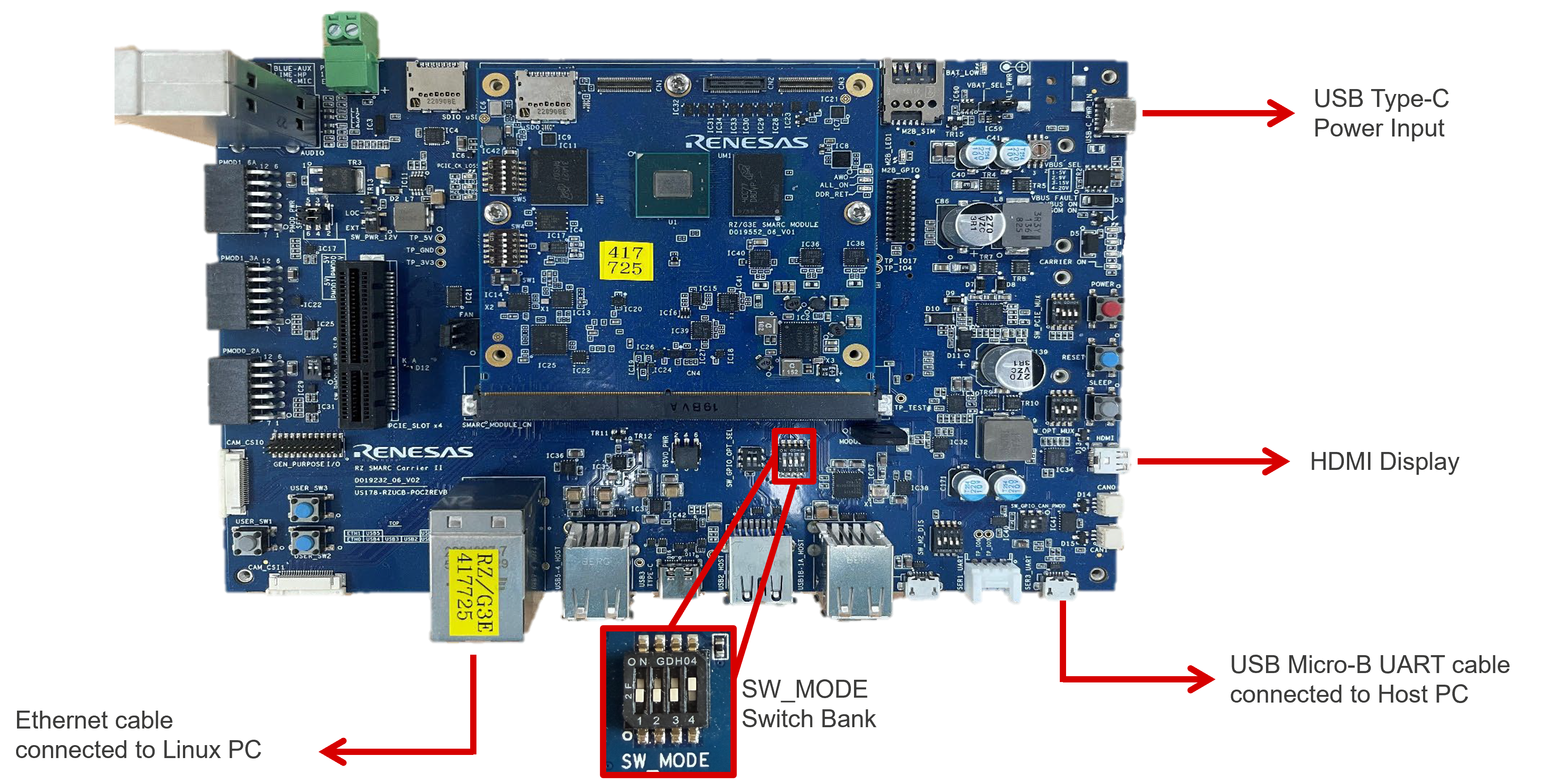
Hardware Setup for Network Boot -
Power ON the board by pressing the POWER button for at least 1 second until the CARRIER ON LED lights up.
The CARRIER ON LED is located above the POWER button.Note
Since the U-Boot environment is saved, autoboot no longer needs to be stopped in the future.
-
Once Linux has booted up, login with
root(no password).