Deploy Prebuilt Binaries
The following prebuilt binaries are used for the eSD boot mode:
core-image-weston-smarc-rzg3e.rootfs.wic.bmap: A map for the WIC image that speeds up flashing by detailing which SD Card blocks need data and which are empty.core-image-weston-smarc-rzg3e.rootfs.wic.gz: Compressed Linux disk image containing the partition table, bootloaders and rootfs (Linux kernel, drivers, applications and system configurations).
By using the eSD boot mode, the bootloaders are loaded directly from the SD Card. This means that there is no need to flash the bootloaders to QSPI separately.
The SD Card can be formatted using a Linux or Windows PC.
Extract Package
Prepare SD Card
-
Connect SD Card to Linux Host PC.
-
Using bmaptool, write the WIC image to the SD Card (replacing /dev/sda with your SD Card device).
-
Make sure all of the data has been written to the SD Card.
-
Eject and remove the SD Card from Linux Host PC.
-
Connect the formatted SD Card to the uSD0 slot on the RZ/G3E.
- Connect SD Card to Windows PC.
- Using balenaEtcher, flash the SD Card with the
core-image-weston-smarc-rzg3e.rootfs.wic.gzfile found under theLinuxdirectory in the package extracted in the previous step. - Once the flash is completed, eject and remove the SD Card.
- Connect the SD Card to the uSD0 slot on the RZ/G3E.
Boot Procedure
Switch Settings
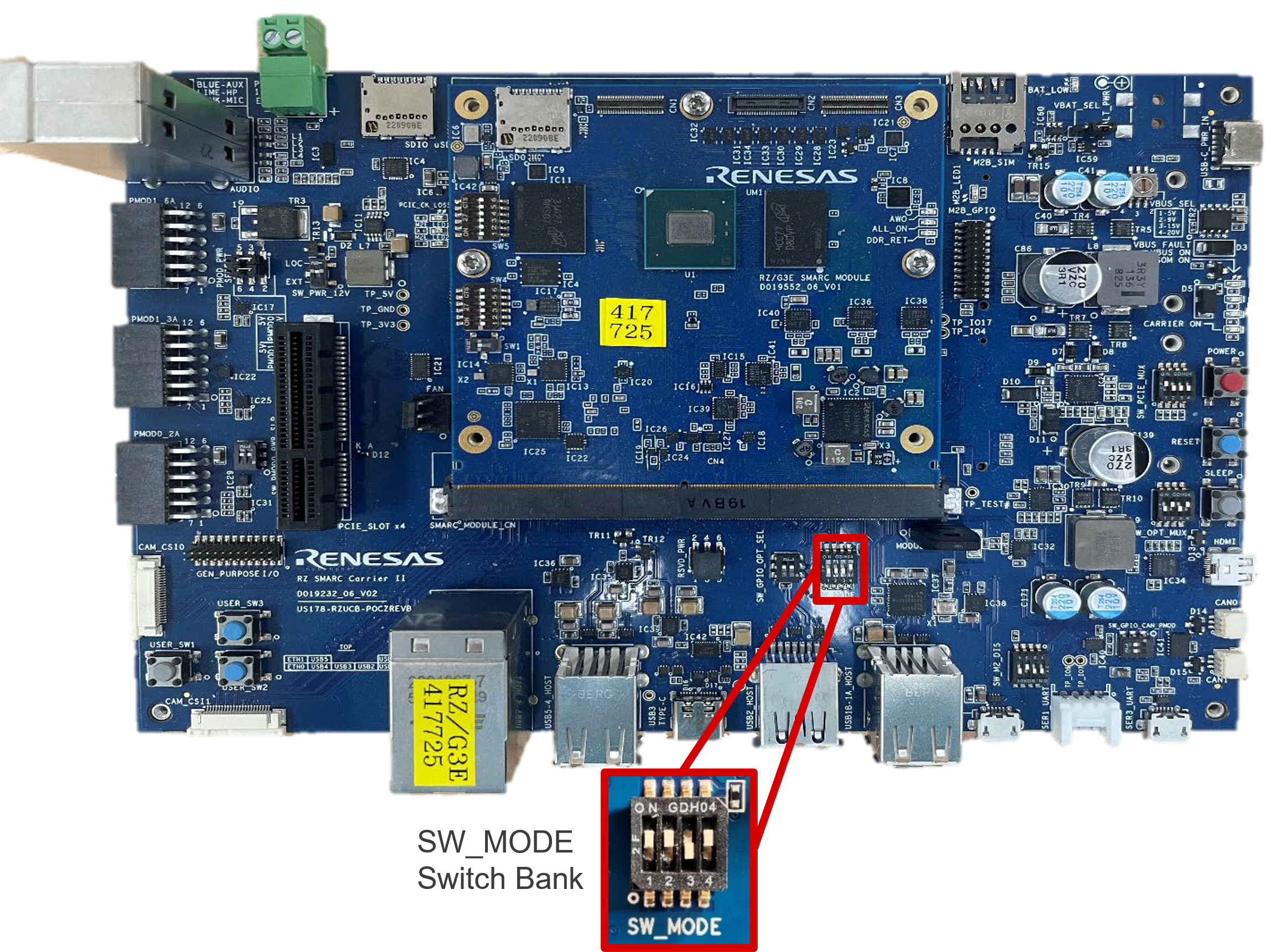
Set SW_MODE switch bank on the SMARC Carrier Board for eSD Boot.
| Switch Bank | SW1 | SW2 | SW3 | SW4 |
|---|---|---|---|---|
| SW_MODE | ON | ON | OFF | ON |
Setup U-Boot Environment
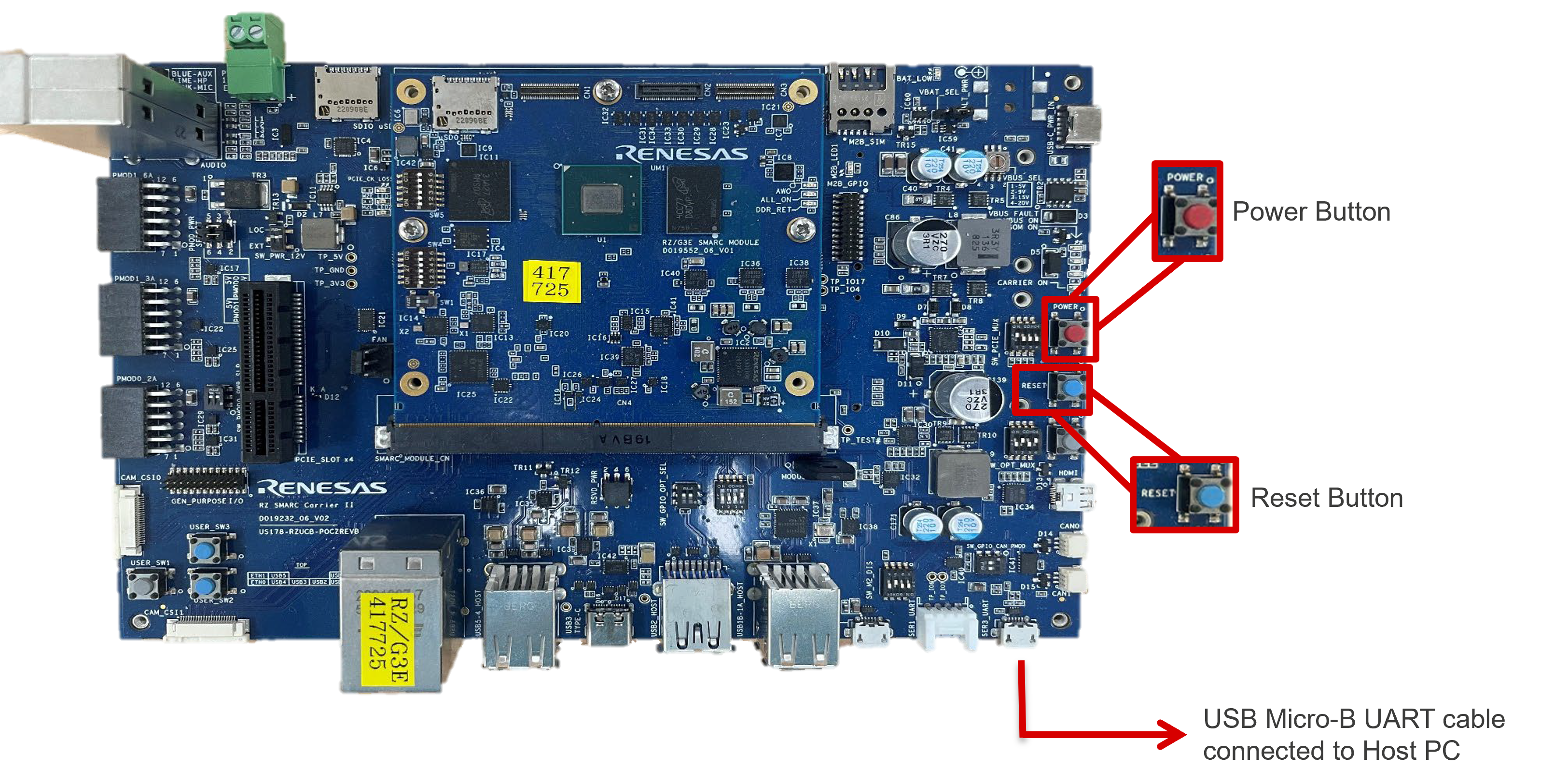
-
Start up a serial terminal connection (e.g. TeraTerm or Minicom) on Host PC, making sure the correct COM port and settings are used.
Variable Value Baud rate 115200bpsData 8 bitParity noneStop 1 bitFlow control none -
Power ON the board by pressing the POWER button for at least 1 second until the CARRIER ON LED lights up.
The CARRIER ON LED is located above the POWER button. -
Press any key to stop the autoboot within 3 seconds of U-Boot starting.
If U-Boot attempts to boot, press the RESET button and try again. -
Set up the U-Boot environment.
-
Power OFF the board by pressing the POWER button for at least 1 second until the CARRIER ON LED turns off.
The CARRIER ON LED is located above the POWER button.
Boot The Board
-
Whilst the board is not powered, confirm that following hardware configuration is being used.
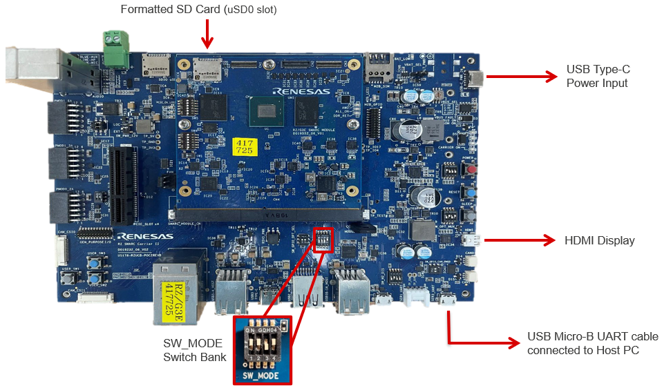
Hardware Setup for eSD Boot -
Power ON the board by pressing the POWER button for at least 1 second until the CARRIER ON LED lights up.
The CARRIER ON LED is located above the POWER button.Note
Since the U-Boot environment is saved, autoboot no longer needs to be stopped in the future.
-
Once Linux has booted up, login with
root(no password).