This software is a set of following files that runs on the evaluation board kit.
Application Source code (C++)
Pre-build application binary
Other necessary files to run the application
Documentation (README.md)
"Getting Started" page (this page) explains how to run the AI Applications.
RZ/V AI SDK
Renesas Website
This software is a development environment for AI Applications.
Provided as a zip file. "Getting Started" page (this page) explains how to use RZ/V AI SDK to run the AI Applications.
RZ/V AI SDK Source Code
Renesas Website
This software is the source code of RZ/V AI SDK that includes Yocto Linux recipe.
Provided as a zip file.
Details and instructions are explained in the following pages.
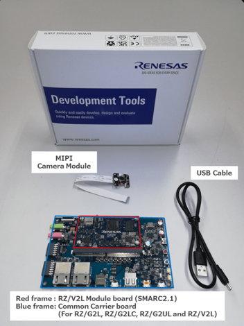
The RZ/V2L EVK is the ideal board kit for RZ/V2L evaluation.
Since MIPI camera module is included, you can start evaluating RZ/V2L immediately by building an environment.
Following items are included in the RZ/V2L EVK.
Equipment
Details
RZ/V2L Evaluation Board
Evaluation board itself.
MIPI Camera Module
Google Coral Camera.
Note that the CMOS sensor (OV5645) in the camera is no longer available, and should not be used for mass production. Any software support provided is for evaluation purposes only.
MicroUSB to Serial Cable
For serial communication between PC and the board.
RZ/V2H EVK
The RZ/V2H EVK is the ideal board kit for RZ/V2H evaluation.
MIPI camera module is not included in EVK.
As an input device, AI Applications support USB camera with VGA (640x480) resolution.
To use MIPI camera, please refer to e-CAM22_CURZH camera provided by e-con Systems.
e-CAM22_CURZH camera supports FHD (1920x1080) resolution.
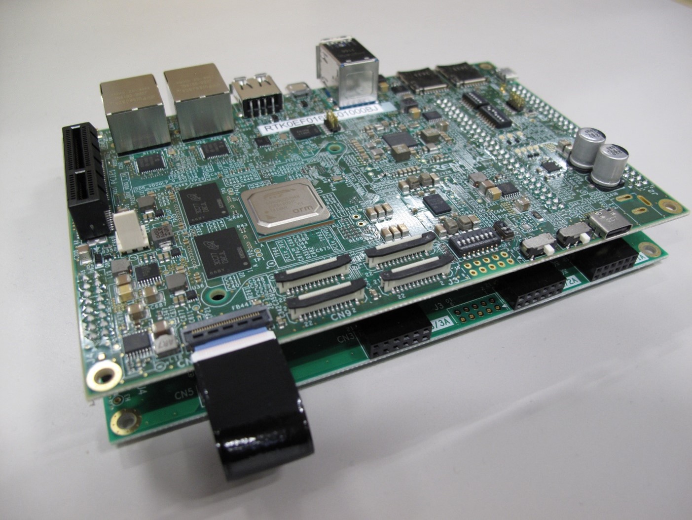
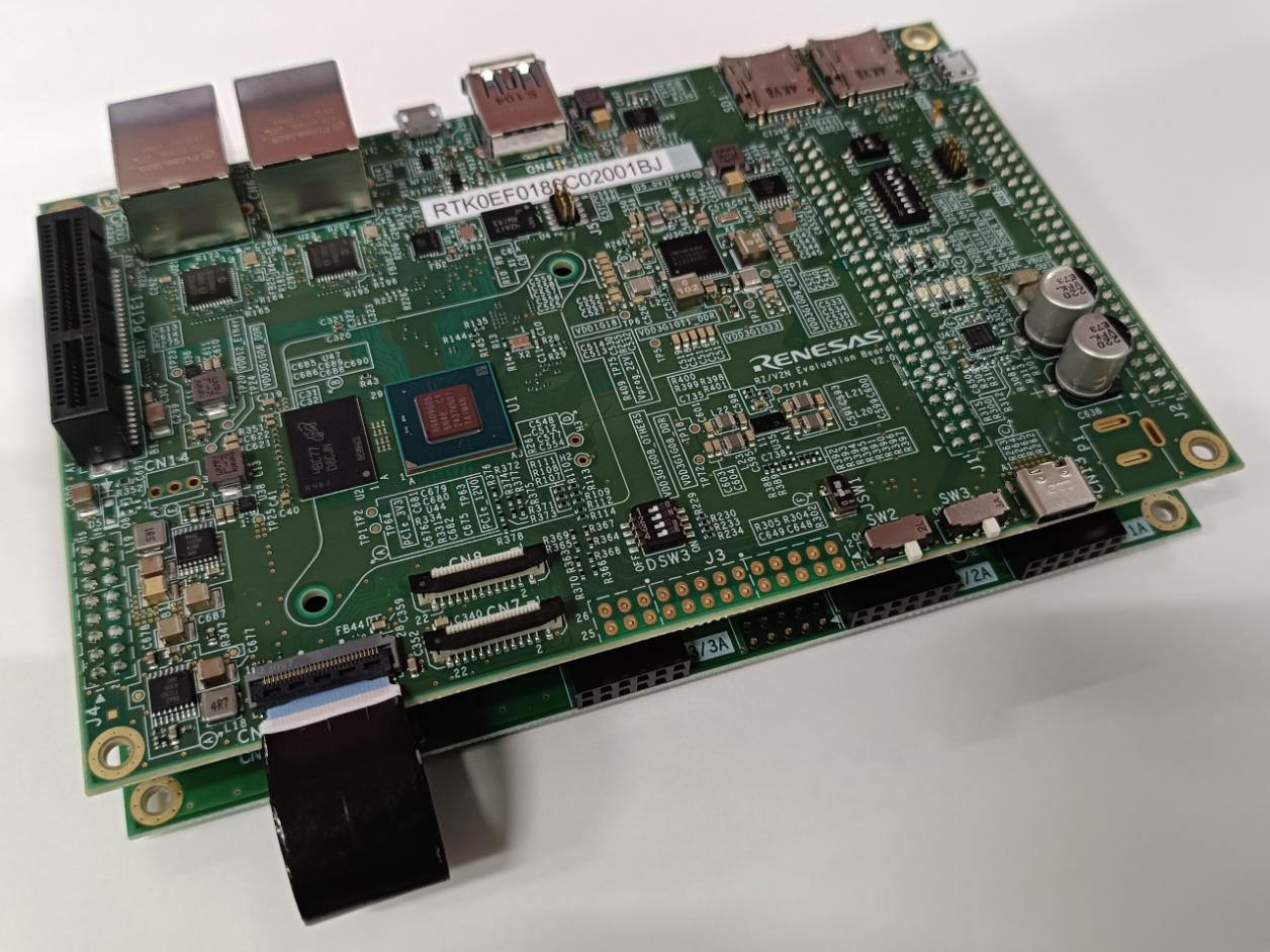
The RZ/V2N EVK is the ideal board kit for RZ/V2N evaluation.
MIPI camera module is not included in EVK.
As an input device, AI Applications support USB camera with VGA (640x480) resolution.
To use MIPI camera, please refer to e-CAM22_CURZH camera provided by e-con Systems.
e-CAM22_CURZH camera supports FHD (1920x1080) resolution.
Following items are included in the RZ/V2N EVK.
Equipment
RZ/V2N Evaluation Board (CPU board) Model Number
Details
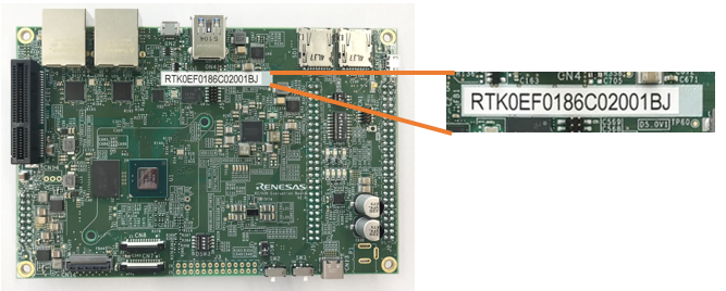
RZ/V2N Evaluation Board V1.0
RTK0EF0186C02000BJ
Evaluation board itself.
RZ/V2N Evaluation Board V2.0
RTK0EF0186C02001BJ
Evaluation board itself.
To check the version of the RZ/V2N EVK, check the model number of the RZ/V2N Evaluation Board (CPU board).
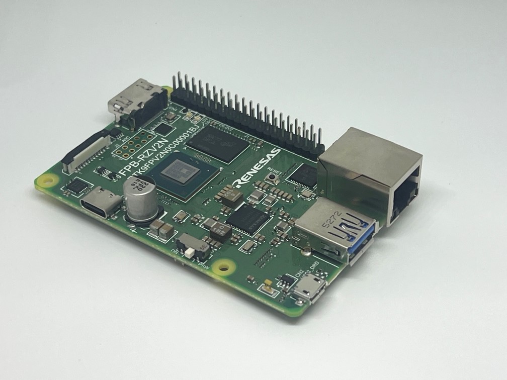
FPB-RZV2N
The FPB-RZV2N is the ideal board kit for fast prototyping.
This board is simple evaluation board that significantly reduces the man-hours required for AI development, allowing easy evaluation.
It can be used in the same way as the RZ/V2N EVK, except for cases that depend on hardware differences.
E.g., Only 1 MIPI camera connector is available on FPB-RZV2N.
As well as EVK, MIPI camera module is not included in FPB.
As an input device, AI Applications support USB camera with VGA (640x480) resolution.
To use MIPI camera, please refer to e-CAM22_CURZH camera provided by e-con Systems.
e-CAM22_CURZH camera supports FHD (1920x1080) resolution.
Following items are included in the FPB-RZV2N.
Equipment
Details
RZ/V2N Fast Prototyping Board
Evaluation board itself.
Step 2: Obtain necessary environment
1. Necessary Equipments
Please prepare the following equipments for your board.
Evaluation Board Kit for RZ/V2L. Includes followings.
MIPI Camera Module(Google Coral Camera)
Note that the CMOS sensor (OV5645) in the camera is no longer available, and should not be used for mass production.
Any software support provided is for evaluation purposes only.
MicroUSB to Serial Cable for serial communication.
AC Adapter
USB Power Delivery adapter for the board power supply.
MicroHDMI Cable
Used to connect the HDMI Monitor and the board.
RZ/V2L EVK has microHDMI port.
USB Camera
Optional. AI Applications support USB camera input.
Supported resolution: 640x480
Supported format: 'YUYV' (YUYV 4:2:2)
Windows PC
Optional. Used as the serial communication console for QSPI Bootloader.
Operating Environment : Windows 11
RZ/V2H
RZ/V2H EVK
Evaluation Board Kit for RZ/V2H.
AC Adapter
USB Power Delivery adapter for the board power supply.
100W is required.
HDMI Cable
Used to connect the HDMI Monitor and the board.
RZ/V2H EVK has HDMI port.
USB Camera
Since RZ/V2H EVK does not include camera module, this will be the standard camera input source.
Supported resolution: 640x480
Supported format: 'YUYV' (YUYV 4:2:2)
To use MIPI camera, please refer to e-CAM22_CURZH provided by e-con Systems.
e-CAM22_CURZH camera supports FHD(1920x1080) resolution.
RZ/V2N
RZ/V2N EVK
or FPB-RZV2N
Evaluation Board Kit for RZ/V2N.
AC Adapter
USB Power Delivery adapter for the board power supply.
60W is required for EVK.
45W is required for FPB.
HDMI Cable
Used to connect the HDMI Monitor and the board.
RZ/V2N EVK/FPB has HDMI port.
USB Camera
Since RZ/V2N EVK/FPB does not include camera module, this will be the standard camera input source.
Supported resolution: 640x480
Supported format: 'YUYV' (YUYV 4:2:2)
To use MIPI camera, please refer to e-CAM22_CURZH provided by e-con Systems.
e-CAM22_CURZH camera supports FHD(1920x1080) resolution.
Common
USB Cable Type-C
Connect AC adapter and the board.
HDMI Monitor
Used to display the graphics of the board.
microSD card
Must have over 16GB capacity of blank space.
Operating Environment: Transcend UHS-I microSD 300S 16GB
Linux PC
Used for Setup microSD card and RZ/V AI SDK Setup.
Operating Environment: Ubuntu 22.04
SD card reader
Used for setting up microSD card.
USB Hub
Used to connect USB Keyboard and USB Mouse to the board.
USB Keyboard
Used to type strings on the terminal of board.
USB Mouse
Used to operate the mouse on the screen of board.
Note
USB camera has different supported resolution and format.
To check the specification of your USB camera, use v4l2-ctl command.
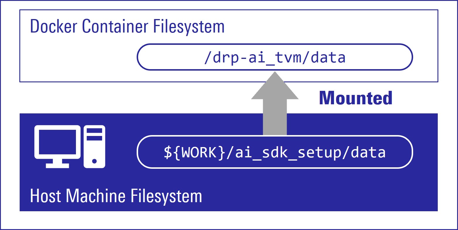
Create new directory to be mounted on Docker container.
mkdir${WORK}/ai_sdk_setup/data
Create docker container. Here, rzv2*_ai_sdk_container is a name of docker container, which can be changed by user.
sudo docker run -it--name rzv2l_ai_sdk_container -v$(pwd)/data:/drp-ai_tvm/data rzv2l_ai_sdk_image
sudo docker run -it--name rzv2h_ai_sdk_container -v$(pwd)/data:/drp-ai_tvm/data rzv2h_ai_sdk_image
sudo docker run -it--name rzv2n_ai_sdk_container -v$(pwd)/data:/drp-ai_tvm/data rzv2n_ai_sdk_image
The local $(pwd)/data is mounted to /drp-ai_tvm/data on the Docker container by the above command option.
For example, you can use this directory to copy files created on the Docker container to your local environment.
To exit docker, run following commands.
exit
To start the docker container again, run the following command.
sudo docker start -i rzv2l_ai_sdk_container
sudo docker start -i rzv2h_ai_sdk_container
sudo docker start -i rzv2n_ai_sdk_container
You have finished the RZ/V AI SDK environment setup.
You are ready to build the AI applications!
Note
Following procedures are for users who would like to build the application from the source code.
If you would like to run the application as quickly as possible, you can skip this step and use pre-build application binary.
Please clone the application respository of your selection and proceed to the next step (Step 7: Deploy AI Application).
E.g., R01_object_detection,
This repository only contains AI Applications for RZ/V2L EVK.
It does not provide instructions for RZ/V AI SDK.
Please refer to the instruction provided in this page.
Check the README.md document provided in application directory and follow the instruction in the chapter called "Application: Build Stage" (or similar) to build the application.
Example:
For R01_object_detection application, follow the instruction in README > Application: Build Stage to generate the following application binary.
object_detection
Note
The git clone command shown in the README.md will download the latest source code and related files.
To download the files of AI Applications v7.10, please specify the version tag by adding -b v7.10 when you running the git clone command as shown below.
Note
The command above will download the latest source code and related files.
To download the files of AI Applications v7.10, please specify the version tag by adding -b v7.10 when you running the git clone command as shown below.
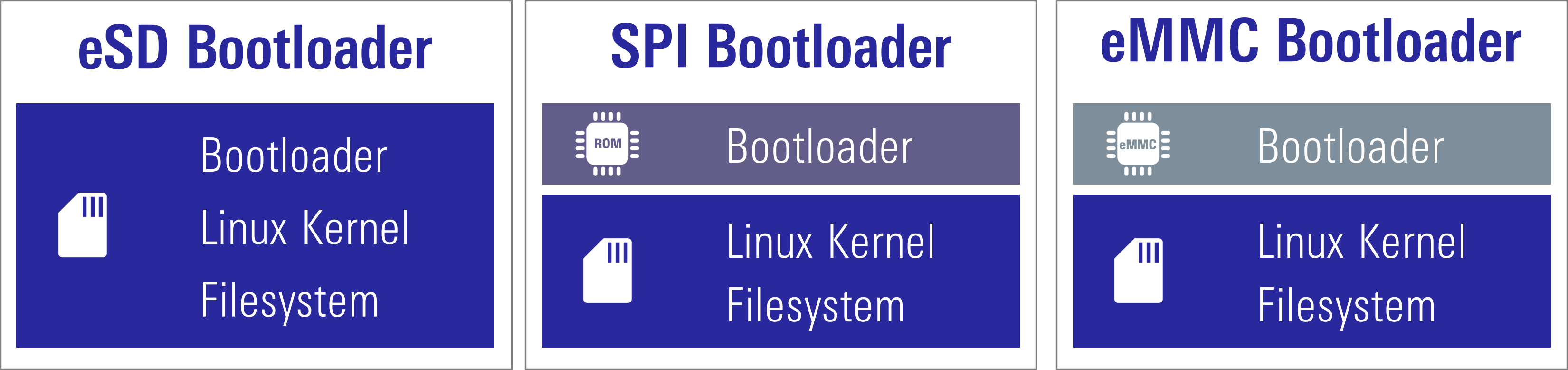
To boot the board, bootloader and other Linux necessary files are required.
Following bootloader types and their corresponding filesystem are available on
RZ/V2L AI SDK
RZ/V2H AI SDK
RZ/V2N AI SDK
.
Type
Description
RZ/V2L EVK
eSD Bootloader
The board boots up using the bootloader written on microSD card.
Linux kernel and filesystem are also on microSD card.
✔
QSPI Bootloader
The board boots up using the bootloader written in Flash ROM on the board.
Linux kernel and filesystem are on microSD card.
✔
Type
Description
RZ/V2H EVK
eSD Bootloader
The board boots up using the bootloader written on microSD card.
Linux kernel and filesystem are also on microSD card.
✔
xSPI Bootloader
The board boots up using the bootloader written in Flash ROM on the board.
Linux kernel and filesystem are on microSD card.
✔
Type
Description
RZ/V2N EVK-ver1
RZ/V2N EVK-ver2
FPB-RZV2N
eSD Bootloader
The board boots up using the bootloader written on microSD card.
Linux kernel and filesystem are also on microSD card.
✔
✔
✔
xSPI Bootloader
The board boots up using the bootloader written in Flash ROM on the board.
Linux kernel and filesystem are on microSD card.
✔
✔
-
eMMC Bootloader
The board boots up using the bootloader written in eMMC on the board.
Linux kernel and filesystem are on microSD card.
Note
Regarding the eSD (Embedded SD) booting, please note the following:
The eSD boot procedure using microSD card described in this guide is for evaluation purposes only.
If you use the eSD boot, please implement the eSD on your board according to the standard "SD Specification Part 1 eSD Addendum (version 2.10)".
The reboot command cannot be used when using the eSD boot procedure using microSD card described in this guide.
The reboot command cannot be used when using the eSD boot procedure using microSD card described in this guide.
Preparation
Click the button
This step contains both eSD and
QSPI Bootloader
xSPI Bootloader
xSPI Bootloader
explanation.
Please click the button below to update the explanation according to your bootloader interface.
For eSD
microSD card needs to contain bootloaders, the Linux kernel and root filesystem to boot-up the board.
RZ/V2L AI SDK
RZ/V2H AI SDK
RZ/V2N AI SDK
supports the WIC format for SD card image.
You can use Linux PC to write the SD card image into microSD card with SD card reader.
Note
This step is required only when starting the AI SDK or when using the new version of AI SDK.
If you have already setup the microSD card with the latest bootloader, Linux kernel, Linux device tree file and root filesystem, skip this step and proceed to the next procedure (2. Deploy Application to the Board).
For xSPI
microSD card needs to contain the Linux kernel and root filesystem to boot-up the board.
RZ/V2L AI SDK
RZ/V2H AI SDK
RZ/V2N AI SDK
supports the WIC format for SD card image.
You can use Linux PC to write the SD card image into microSD card with SD card reader.
Bootloaders must be written in Flash ROM on the board.
You can use Windows PC to write the bootloaders on Flash ROM.
Note
This step is required only when starting the AI SDK or when using the new version of AI SDK.
If you have already setup the microSD card and the bootloader written in Flash ROM on the board, skip this step and proceed to the next procedure (2. Deploy Application to the Board).
Note
The size of WIC format SD card image is 16GB.
If you would like to expand the SD card image size,
please build the RZ/V2L AI SDK Source Code according to How to Build RZ/V2L AI SDK.
please build the RZ/V2H AI SDK Source Code according to How to Build RZ/V2H AI SDK.
please build the RZ/V2N AI SDK Source Code according to How to Build RZ/V2N AI SDK.
Install Necessary Software
As explained in Necessary Software of Getting Started Step 2, make sure that bmap-tools is installed on Linux PC.
If you have not installed the bmap-tools, install it using following command on Host PC (Not in the docker container).
sudo apt install bmap-tools
Write the Linux files to SD card
For eSD
Run the below command to decompress ${WORK}/board_setup/eSD.zip.
cd${WORK}/board_setup
unzip eSD.zip
Following files are necessary.
They are in the ${WORK}/board_setup/eSD directory.
For QSPI
Run the below command to decompress ${WORK}/board_setup/QSPI.zip.
cd${WORK}/board_setup
unzip QSPI.zip
Following files are necessary.
They are in the ${WORK}/board_setup/QSPI directory.
File
Description
core-image-weston-smarc-rzv2l.rootfs.wic.bmap
SD card image
core-image-weston-smarc-rzv2l.rootfs.wic.gz
For xSPI
Run the below command to decompress ${WORK}/board_setup/xSPI.zip.
cd${WORK}/board_setup
unzip xSPI.zip
Following files are necessary.
They are in the ${WORK}/board_setup/xSPI directory.
File
Description
core-image-weston-rzv2h-evk.rootfs.wic.bmap
SD card image
core-image-weston-rzv2h-evk.rootfs.wic.gz
For xSPI
Run the below command to decompress ${WORK}/board_setup/xSPI.zip.
cd${WORK}/board_setup
unzip xSPI.zip
Following files are necessary.
They are in the ${WORK}/board_setup/xSPI directory.
File
Description
core-image-weston-rzv2n-evk.rootfs.wic.bmap
SD card image
core-image-weston-rzv2n-evk.rootfs.wic.gz
Follow the instruction below to prepare the microSD card.
Before inserting the microSD card to your Linux PC, open the terminal on Linux PC and run the following command to check the devices without microSD card.
lsblk
Following is the example output.
NAME MAJ:MIN RM SIZE RO TYPE MOUNTPOINT
sda 8:0 0 30.9G 0 disk
├─sda1 8:1 0 512M 0 part /boot/efi
├─sda2 8:2 0 1K 0 part
└─sda5 8:5 0 30.3G 0 part /
sr0 11:0 1 1024M 0 rom
Insert the microSD card to your Linux PC and run the following command again.
lsblk
Check the output and confirm the name appeared. This would be your microSD card device name.
Following is the example output.
NAME MAJ:MIN RM SIZE RO TYPE MOUNTPOINT
sda 8:0 0 30.9G 0 disk
├─sda1 8:1 0 512M 0 part /boot/efi
├─sda2 8:2 0 1K 0 part
└─sda5 8:5 0 30.3G 0 part /
sdb 8:16 1 29.7G 0 disk
└─sdb1 8:17 1 29.7G 0 part
sr0 11:0 1 1024M 0 rom
In this case, followings are your microSD card configuration.
/dev/sdb: The device name for the entire microSD card.
/dev/sdb1: The partition name in microSD card. There may be multiple sdb* depending on the microSD card.
Warning
Be careful not to use the name of other device since it may destruct your computer filesystem.
To use bmaptools, microSD card partitions must be unmounted.
Run the following command to check the automatically mounted microSD card partitions.
df-h
Check the output and find the mount point, which is "/media/user/9016-4EF8" in the following example.
Filesystem      Size  Used Avail Use% Mounted on
:
snip
:
/dev/sdb1        15G   32K   15G   1% /media/user/9016-4EF8
Warning
Here, we use "/dev/sdb" as microSD card device name.
Unmount the automatically mounted partitions.
sudo umount /media/user/9016-4EF8
Note
If there are more than one partitions on microSD card, unmount all partitions.
Run the following command to mount the partition 2, which contains the root filesystem.
sudo mkdir /mnt/sd -psudo mount /dev/sdb2 /mnt/sd
Warning
Change /dev/sdb to your microSD card device name.
Create the application directory on root filesystem.
sudo mkdir /mnt/sd/home/weston/tvm
Note
Directory name tvm can be determined by user.
Copy the necessary files in execution environment.
Select the appropriate option below based on the application type explained in Getting Started Step 6.
Option 1: <Application 1>
Check the README.md document provided in application directory and follow the instruction in the chapter called "Application: Deploy Stage" (or similar) to deploy the application.
Note
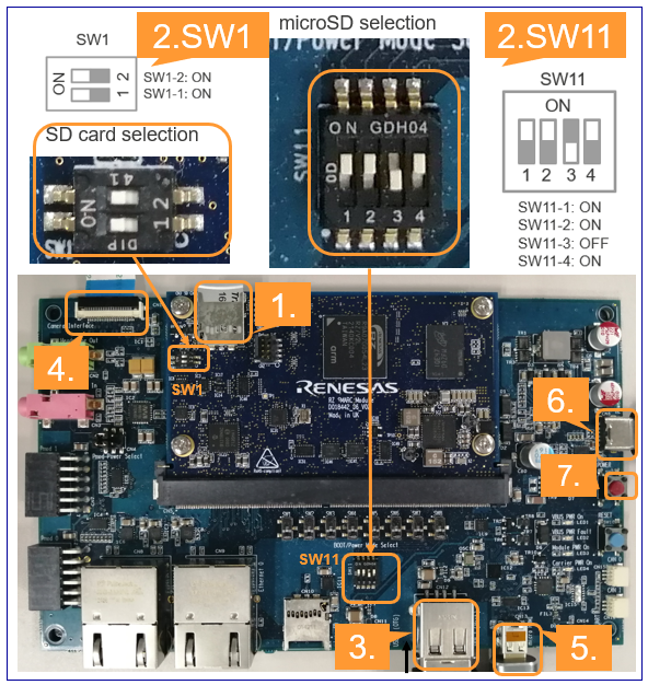
Use the microSD card slot CN3 as shown in the figure.
Change SW1 and SW11 setting as shown in the figure.
Connect the USB mouse and USB keyboard via USB hub.
Connect the Google Coral camera to the Board.
Connect the HDMI monitor to the Board.
Connect the power cable to the Board.
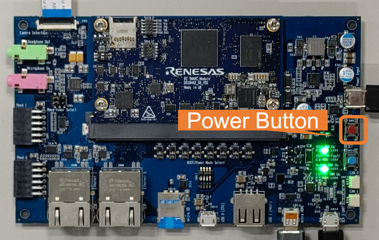
Press power button for 1 second to turn on the board.
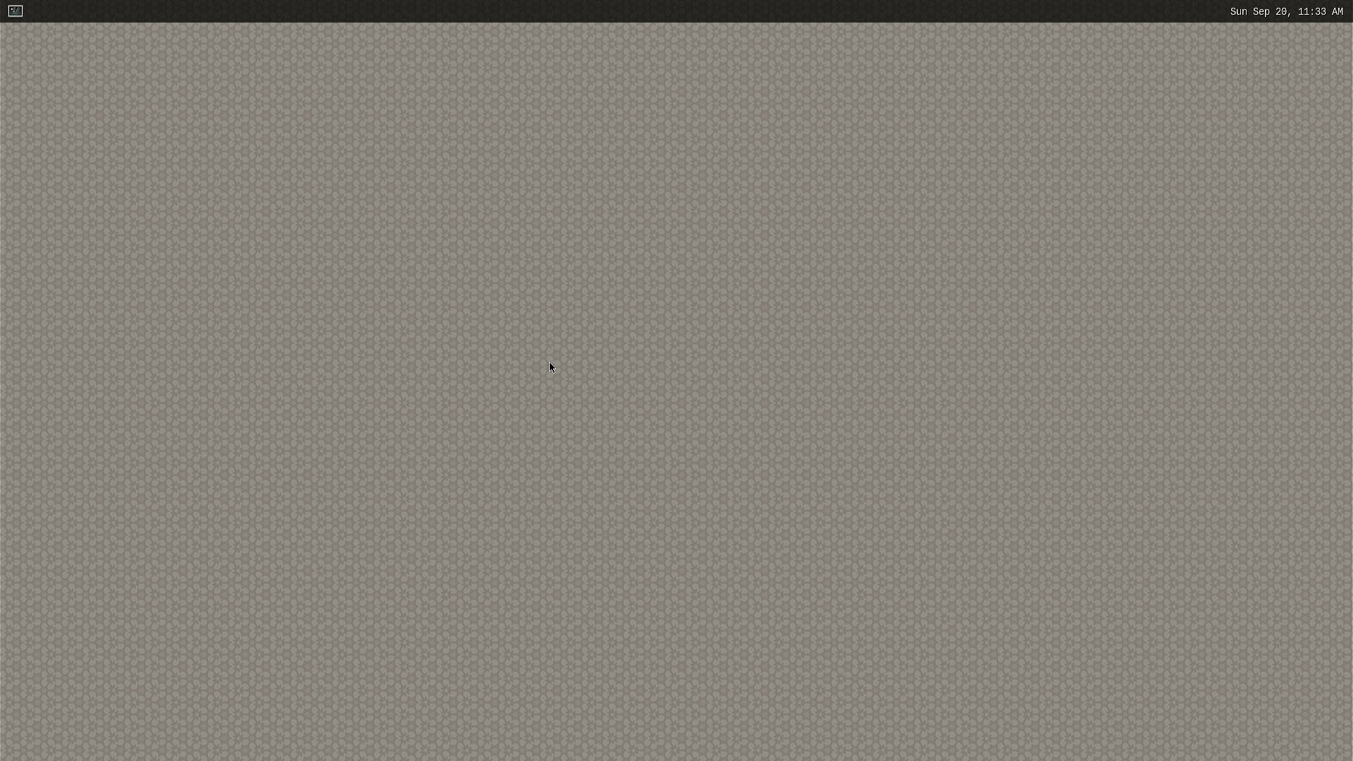
After the boot-up, following screen will be displayed on HDMI monitor.
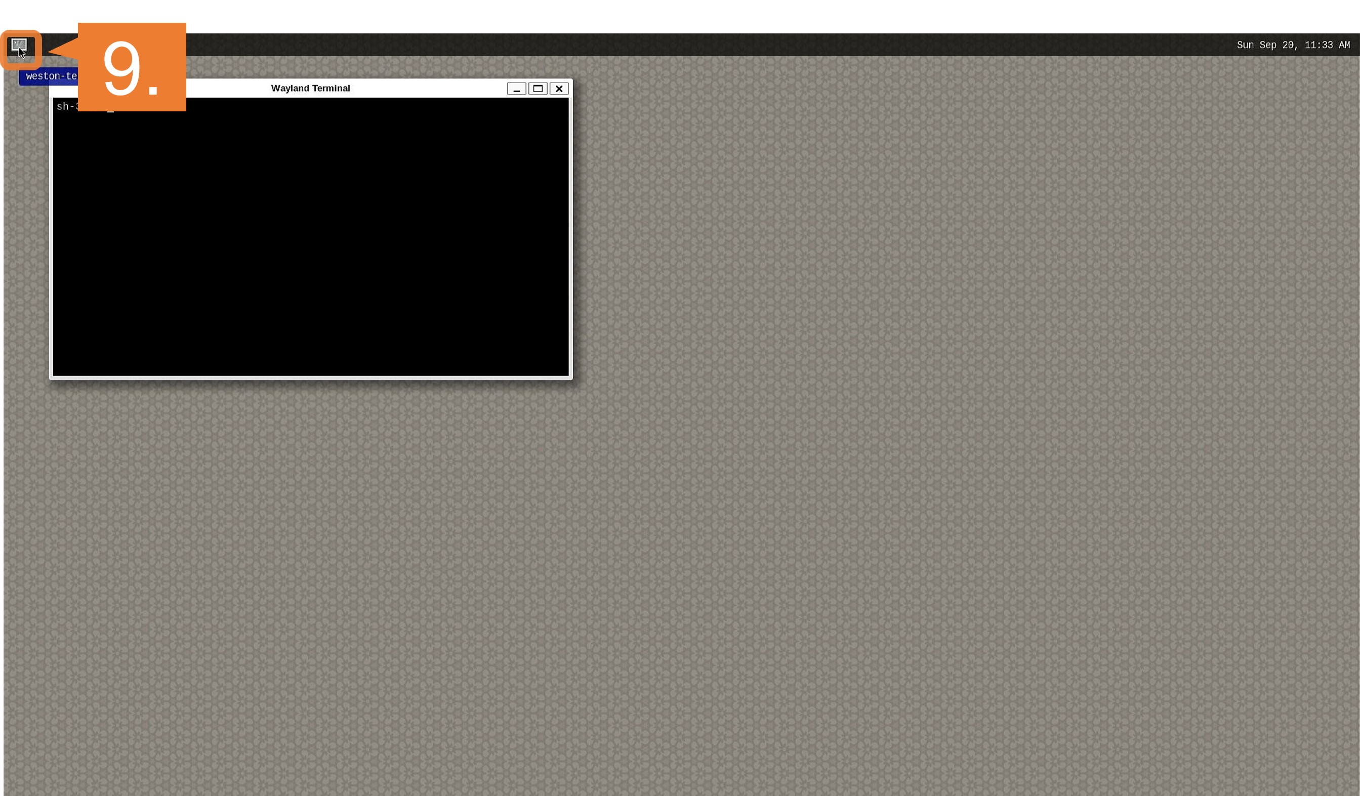
Click the icon at the top-left corner to open the terminal.
For QSPI
Note
After bootloader is written and U-boot setting is changed, terminal emulator is no longer needed.
Users can detach the serial port connection.
Insert the microSD card to the Board.
Note
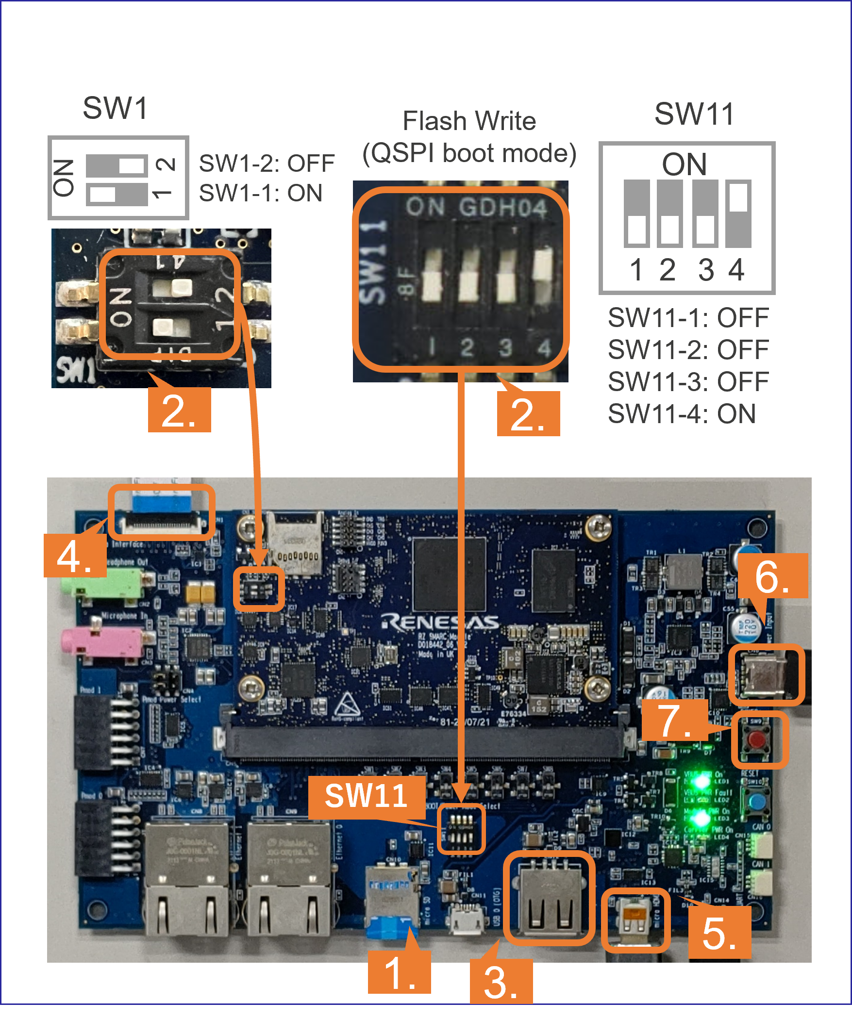
Use the microSD card slot CN10 as shown in the figure.
Change SW1 and SW11 setting as shown in the figure.
Connect the USB mouse and USB keyboard via USB hub.
Connect the Google Coral camera to the Board.
Connect the HDMI monitor to the Board.
Connect the power cable to the Board.
Press power button for 1 second to turn on the board.
After the boot-up, following screen will be displayed on HDMI monitor.
Click the icon at the top-left corner to open the terminal.
For eSD
Insert the microSD card to the Board.
Note
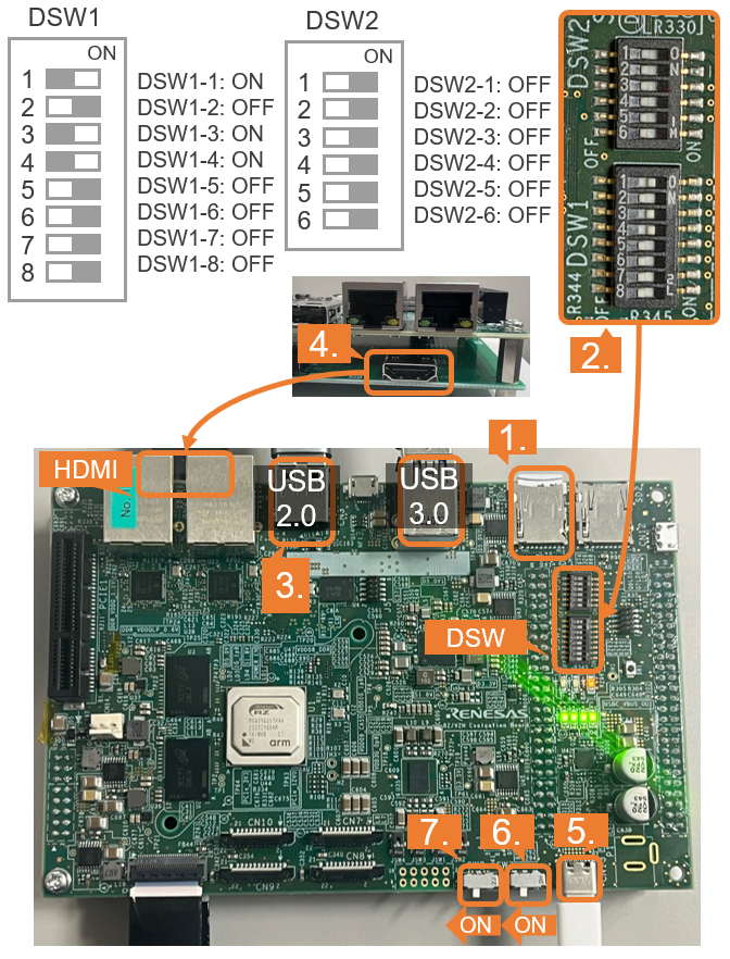
Use the microSD card slot SD1 on the Board as shown in the figure.
Change DSW1 and DSW2 setting as shown in the figure.
Connect the USB mouse and USB keyboard and USB camera via USB hub.
Note
There are USB 2.0 port and USB 3.0 port on RZ/V2H EVK.
Please connect your USB camera to appropriate port according to its requirement.
Here, USB camera is connected to USB 2.0 via USB hub.
Connect the HDMI monitor to the Board.
Connect the power cable to the Board.
Turn the SW3 to ON.
Turn the SW2 to ON to power on the Board
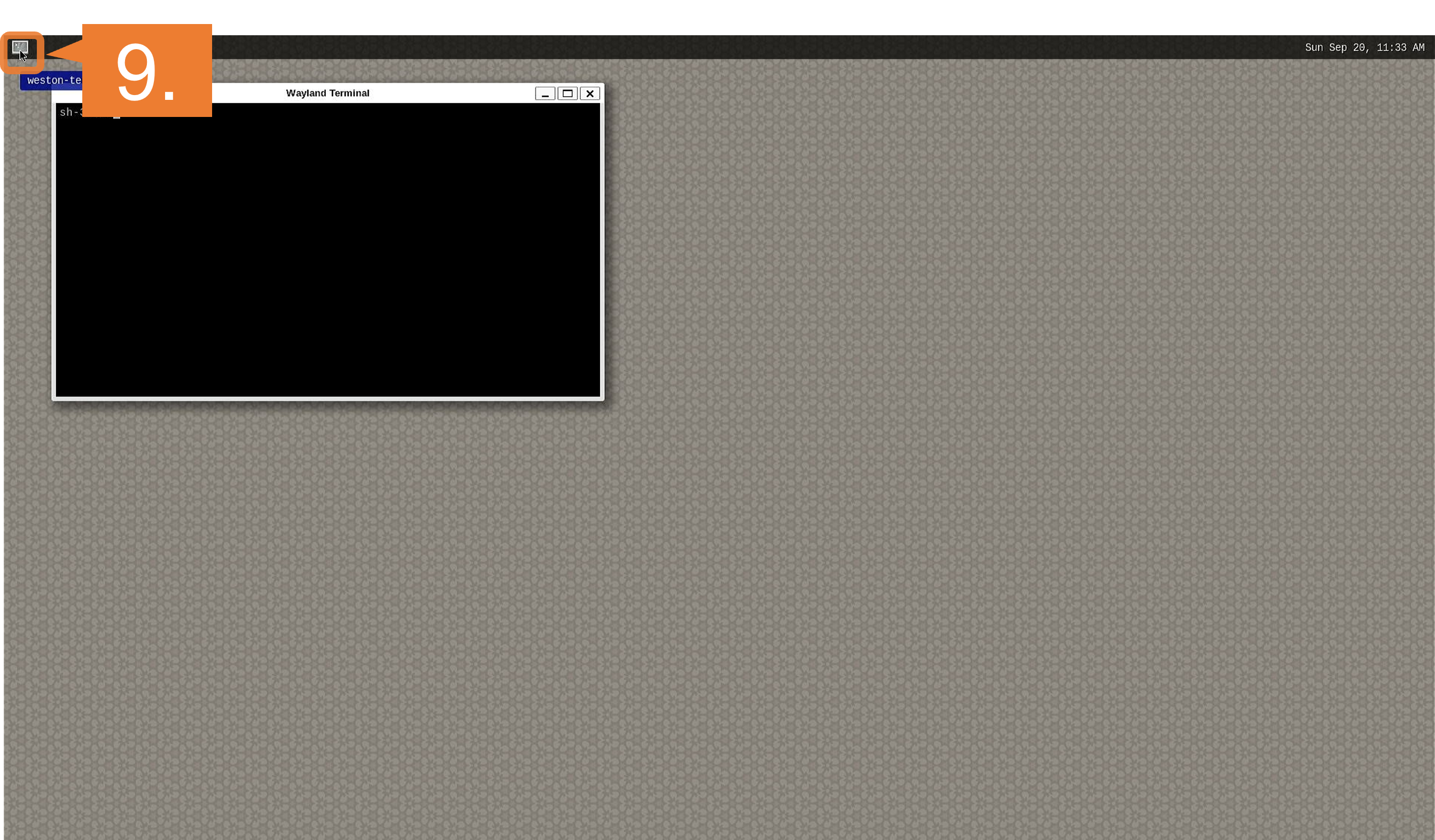
After the boot-up, following screen will be displayed on HDMI monitor.
Click the icon at the top-left corner to open the terminal.
For xSPI
Note
After bootloader is written and U-boot setting is changed, terminal emulator is no longer needed.
Users can detach the serial port connection.
Insert the microSD card to the Board.
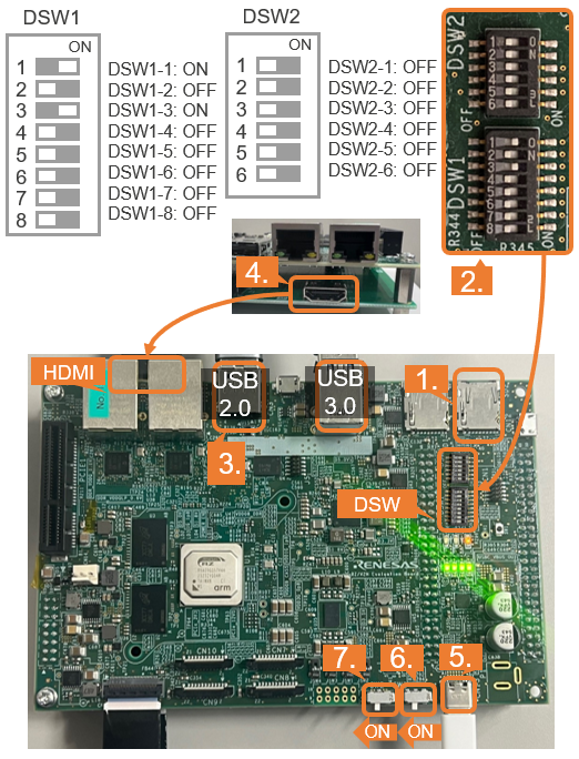
Note
Use the microSD card slot SD2 on the Board as shown in the figure.
Change DSW1 and DSW2 setting as shown in the figure.
Connect the USB mouse and USB keyboard and USB camera via USB hub.
Note
There are USB 2.0 port and USB 3.0 port on RZ/V2H EVK.
Please connect your USB camera to appropriate port according to its requirement.
Here, USB camera is connected to USB 2.0 via USB hub.
Connect the HDMI monitor to the Board.
Connect the power cable to the Board.
Turn the SW3 to ON.
Turn the SW2 to ON to power on the Board
After the boot-up, following screen will be displayed on HDMI monitor.
Click the icon at the top-left corner to open the terminal.
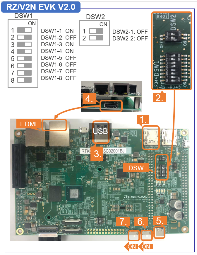
Note
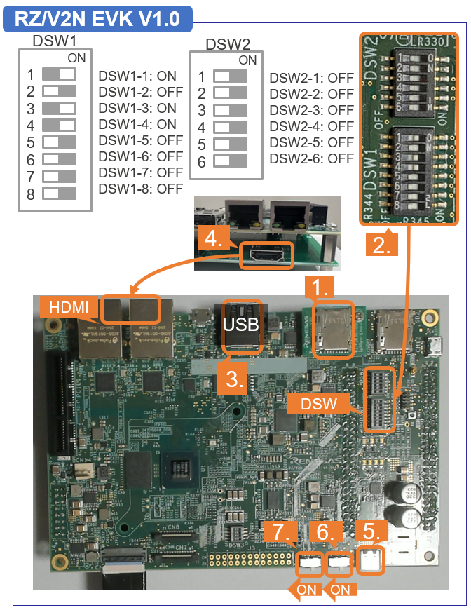
Use the microSD card slot SD1 on the Board as shown in the figure.
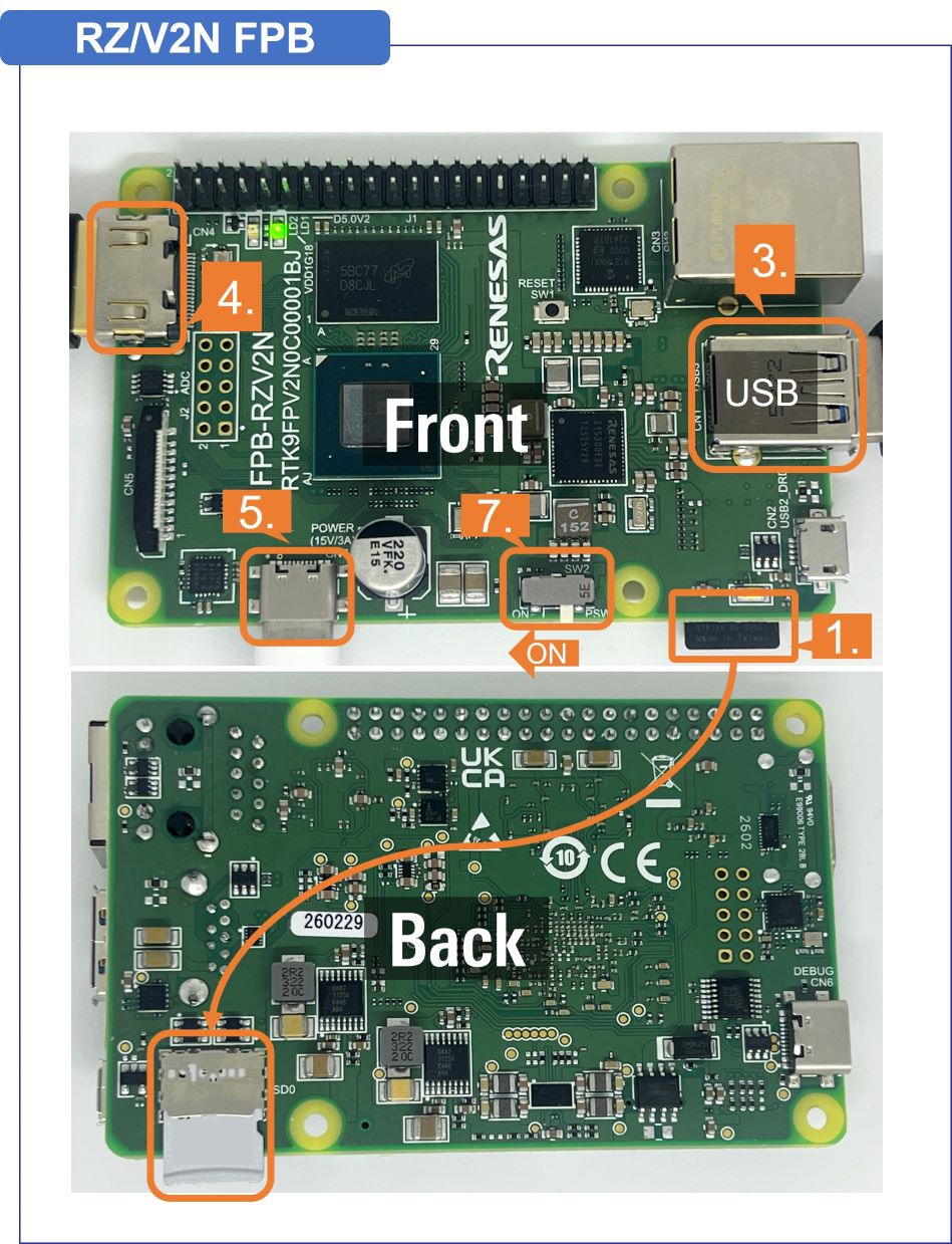
Use the microSD card slot on the back of the Board as shown in the figure.
[EVK only]Change DSW1 and DSW2 setting as shown in the figure.
Connect the USB mouse and USB keyboard and USB camera via USB hub.
Note
There are USB 2.0 port and USB 3.0 port on RZ/V2N EVK.
Please connect your USB camera to appropriate port according to its requirement.
Here, USB camera is connected to USB 3.0 via USB hub.
Connect the HDMI monitor to the Board.
Connect the power cable to the Board.
[EVK only]Turn the SW3 to ON.
Turn the SW2 to ON to power on the Board
After the boot-up, following screen will be displayed on HDMI monitor.
Click the icon at the top-left corner to open the terminal.
For xSPI
Note
After bootloader is written and U-boot setting is changed, terminal emulator is no longer needed.
Users can detach the serial port connection.
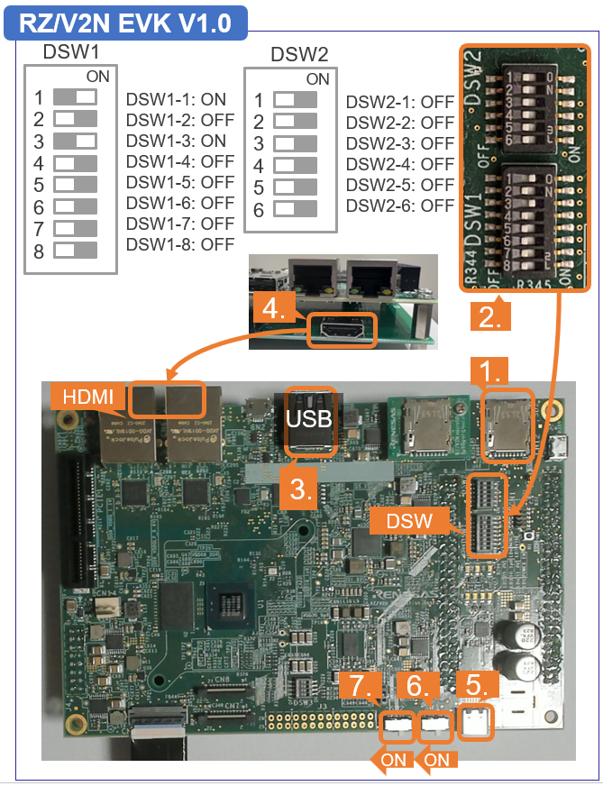
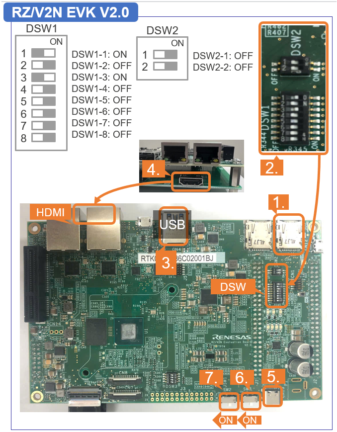
Insert the microSD card to the Board.
Note
Use the microSD card slot SD2 on the Board as shown in the figure.
Change DSW1 and DSW2 setting as shown in the figure.
Connect the USB mouse and USB keyboard and USB camera via USB hub.
Note
There are USB 2.0 port and USB 3.0 port on RZ/V2N EVK.
Please connect your USB camera to appropriate port according to its requirement.
Here, USB camera is connected to USB 3.0 via USB hub.
Connect the HDMI monitor to the Board.
Connect the power cable to the Board.
Turn the SW3 to ON.
Turn the SW2 to ON to power on the Board
After the boot-up, following screen will be displayed on HDMI monitor.
Click the icon at the top-left corner to open the terminal.
After Step 7, users should have completed followings.
Setup miroSD card.
Deploy the application on miroSD card.
Boot the board.
Step 8: Run AI Application
This section explains how to run the AI Application.
Follow the instructions explained in the document (README.md) of applications on GitHub.
Example:
For R01_object_detection application, follow the instruction in README > Application: Run Stage to run the application.
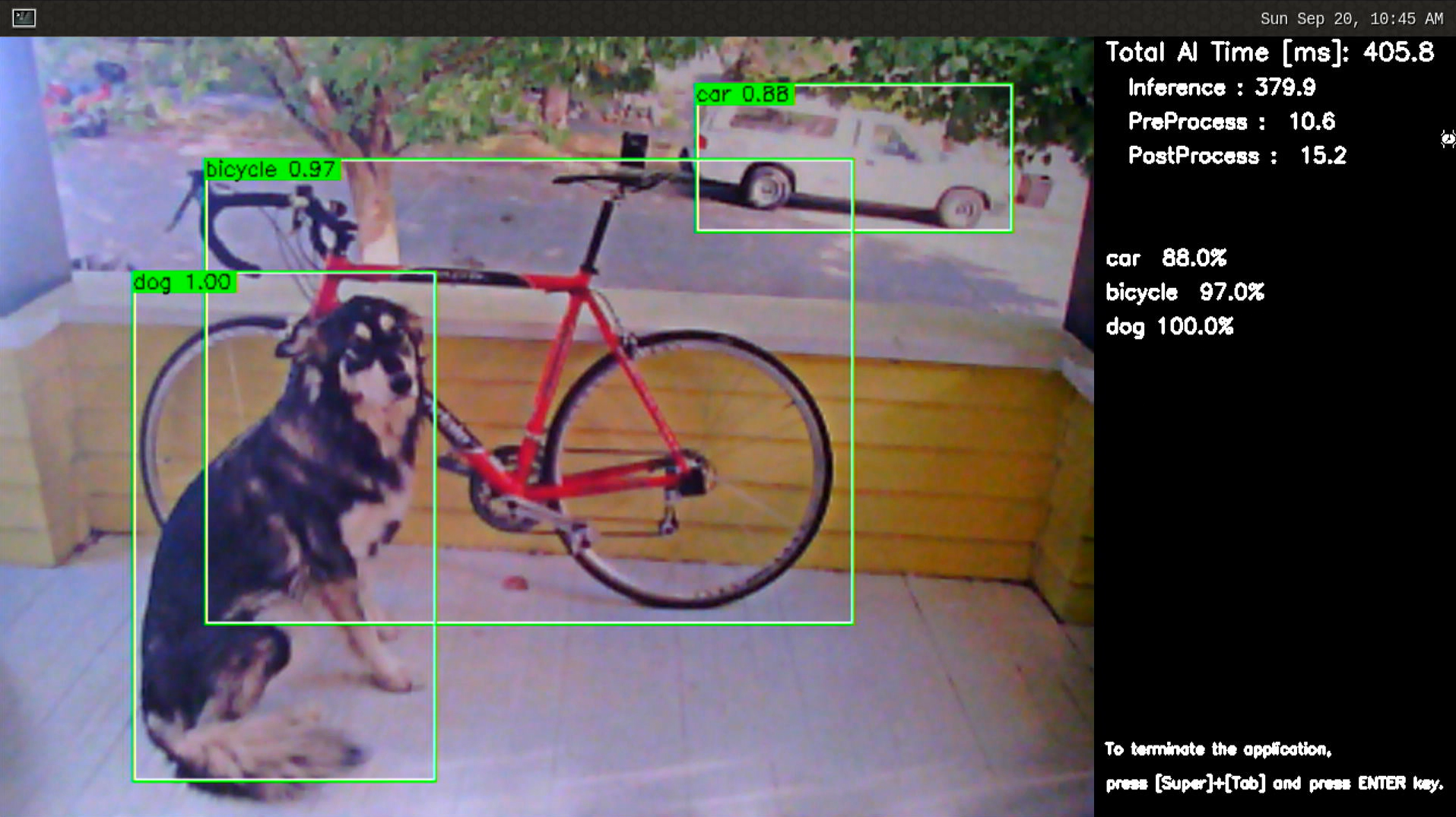
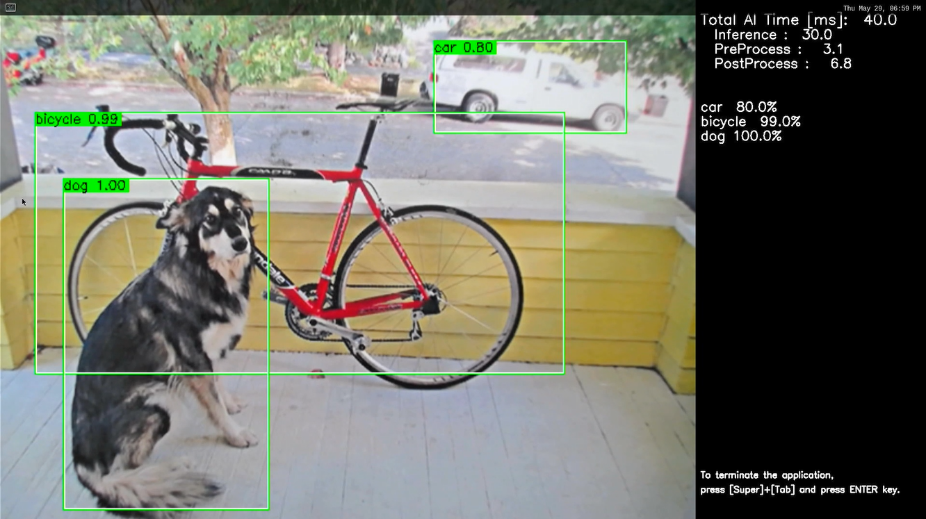
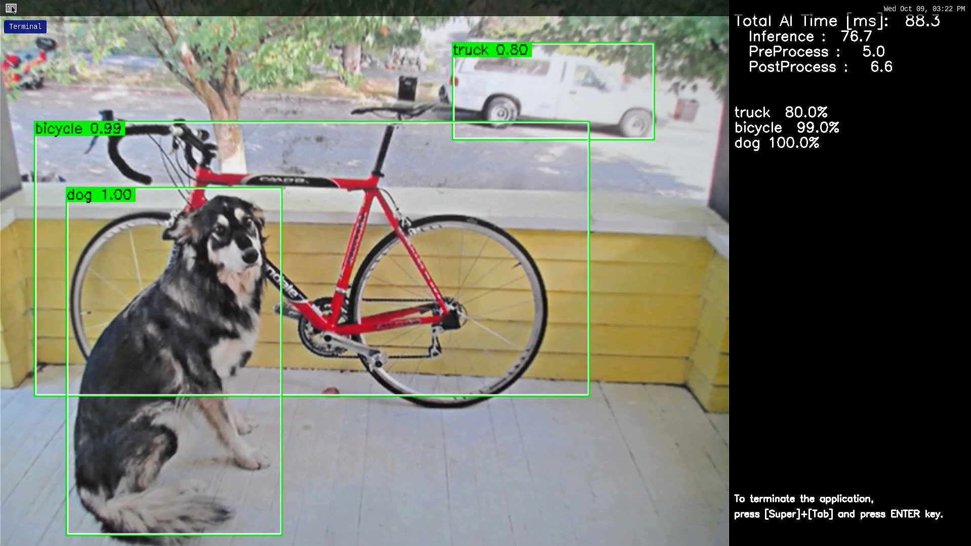
If you have successfully run the application, you will see following window on HDMI screen.
Note1
When running an AI Application, the following warning may be shown. It does not affect the operation.
[ WARN:0@xx.xxx] global cap_gstreamer.cpp:1777 open OpenCV | GStreamer warning: Cannot query video position: status=0, value=-1, duration=-1
Step 9: Shutdown the Board
This section explains how to shutdown the target board.
On the screen, check that shutdown procedure runs and the HDMI display is blacked out.
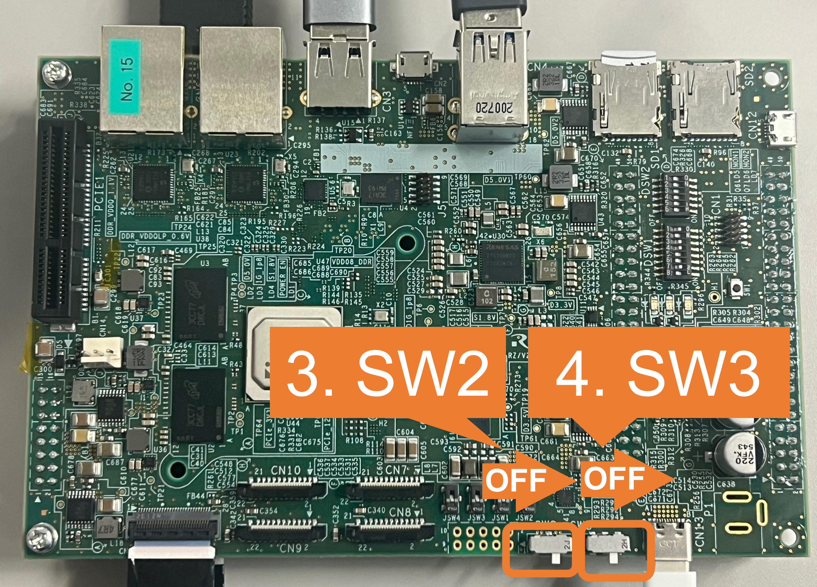
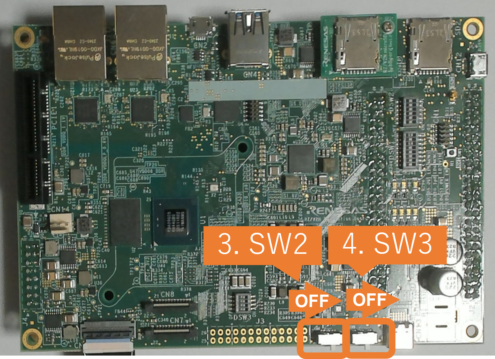
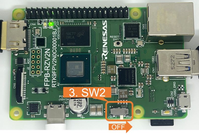
Turn SW2 to OFF.
[EVK only] Turn SW3 to OFF.
This is the end of Getting Started.
You have experienced the AI Application development procedures.
Next step is to change the application to create your own AI Application.
You can use the applications listed in AI Applications to expand your ideas!
If you would like to customize Yocto Linux or develop your own board, please change and build the AI SDK Source Code based on your environment.
Please refer to How to Build AI SDK page shown below for more details.