Renesas
RZ/V AI
The best solution for
starting your AI applications.
Provided by Renesas Electronics Corporation


To keep you updated,
Watch our GitHub repository
Watch
This project is maintained by renesas-rz
Hosted on GitHub Pages — Theme by orderedlist
Developer's Guide
This page explains the additional information of How to Build RZ/V AI SDK for Linux developers.
Terminology
Contents
| ID | Title | Device | Target |
|---|---|---|---|
| D1 | Change the size of the microSD card image in WIC format |
RZ/V2H RZ/V2N |
AI SDK Source Code v5.20 AI SDK Source Code v5.00 |
| D2 | How to boot from QSPI | RZ/V2L | AI SDK Source Code v5.00 |
| D3 | How to boot from xSPI |
RZ/V2H RZ/V2N |
AI SDK Source Code v5.20 AI SDK Source Code v5.00 |
| D4 | How to boot from eMMC | RZ/V2N | AI SDK Source Code v5.00 |
D1. For RZ/V2H, RZ/V2N: Change the size of the microSD card image in WIC format
This section explains how to change the microSD card image size by changing the build settings of the WIC file.
Note
This instruction assumes that you have completed the steps in How to build RZ/V AI SDK Source Code below.
RZ/V2H: Step 3-10
RZ/V2N: Step 3-10
- Open
${YOCTO_WORK}/build/conf/local.conffile in a text editor. - Find the following text in the file and edit the highlighted value to define the disk space of the image in Kbytes.
The table below shows examples of setting values written in... # Support WIC images with default wks from WKS_DEFAULT_FILE # Reupdate WKS_DEFAULT_FILE if want to support another wks file. WKS_SUPPORT ?= "1" WKS_DEFAULT_FILE_rzv2h-dev = "rz-image-bootpart-mmc.wks" WKS_DEFAULT_FILE_rzv2h-evk-alpha = "rz-image-bootpart-esd_rzv2h.wks" WKS_DEFAULT_FILE_rzv2h-evk-ver1 = "rz-image-bootpart-esd_rzv2h.wks" # Defines additional free disk space created in the image in Kbytes. IMAGE_ROOTFS_EXTRA_SPACE = "8388608" ...local.conffile.
Note If you have customized Linux, the disk image size may differ from the table.SD card image size
(Gbytes)Setting values in the "local.conf" file
(Kbytes)4 1048576 8 4194304 16 8388608 (default)
D2. For RZ/V2L: How to boot from QSPI
This section explains how to setup the board for QSPI Bootloader.
Note
This step is required only when starting the AI SDK or when using the new version of AI SDK.
If you have already setup the microSD card and the bootloader written in QSPI on the board, skip this step and proceed to the next step (Step7:2. Deploy Application to the Board in Getting Started).
Follow the instruction below to setup the board.
If you have already setup the microSD card and the bootloader written in QSPI on the board, skip this step and proceed to the next step (Step7:2. Deploy Application to the Board in Getting Started).
Note
Explanation in this step is for QSPI Bootloader, which requires Windows PC as serial communication console.
-
1. Install Terminal Emulator
-
Install following software on Windows PC to be used as serial communication console.
-
Terminal emulator
- Operating Environment: Tera Term
-
Terminal emulator
-
Install following software on Windows PC to be used as serial communication console.
-
2. Install the serial port driver
Note If you have already installed the serial port driver, skip this step and proceed to next procedure.The serial communication between Windows PC and RZ/V2L EVK requires following driver.
https://ftdichip.com/drivers/vcp-drivers/
- Download the software "Virtual COM port (VCP) driver" from the windows version "setup executable" on the download page and extract it.
-
Run the
*.exefile extracted to install the serial port driver.
-
3. Write bootloaders to QSPI on the board
- Copy following files to your Windows PC.
Path File name Description ${WORK}/board_setup/QSPI/bootloader Flash_Writer_SCIF_RZV2L_SMARC_PMIC_DDR4_2GB_1PCS.mot
bl2_bp-smarc-rzv2l_pmic.srec
fip-smarc-rzv2l_pmic.srecDirectory path and files when using files included with RZ/V2L AI SDK ${YOCTO_WORK}/build/tmp/deploy/images/smarc-rzv2l Directory path and files when using files generated with How to build RZ/V2L AI SDK Source Code - Connect Windows PC and Board via Serial to MicroUSB Cable.
- Change SW1 and SW11 setting (see the figure below).
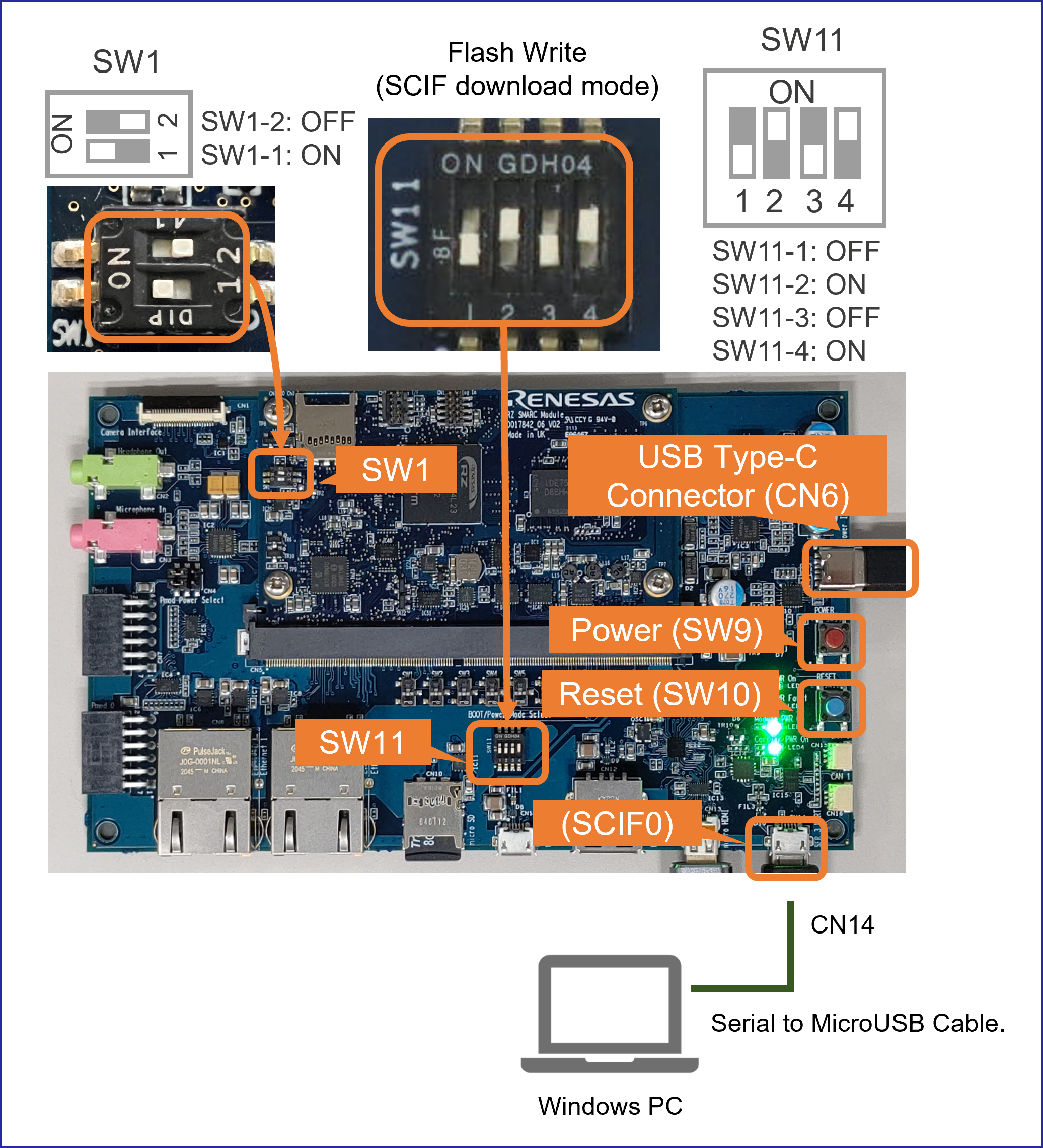
- Connect the power cable to CN6 on the Board.
- Press and hold the power button (SW9) for 1 second to turn on the power.
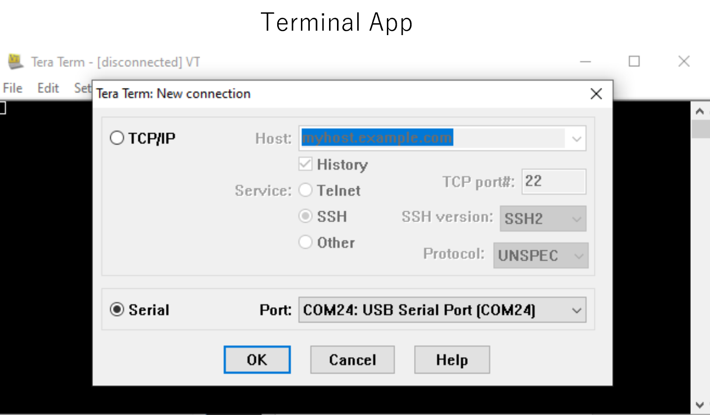
- On Windows PC, open the terminal emulator. Here, we use Tera Term as an example.
- Select "File" > "New Connection" and select "Serial" port as shown below.
- Open the configuration window from the "Setup">"Terminal" and change the setting as follows.
Item Value New-line Receive: Auto Transmit: CR - Open the configuration window from the "Setup">"Serial port" and change the setting as follows.
Item Value Baud rate 115200 Data 8bit Parity none Stop 1bit Flow control none Transmit delay 0msec/char - Press the reset button (SW10) and following message will be displayed on the terminal.
SCIF Download mode (C) Renesas Electronics Corp. -- Load Program to System RAM --------------- please send ! -
Open "File" > "Send file..." and send the Flash Writer file (
*.mot) as a text.
If following message is displayed, the file transfer suceeded.Flash writer for RZ/V2 Series Vx.xx xxx.xx,20xx Product Code : RZ/V2L > - Enter "
XLS2" on the terminal to get following messages.> XLS2 ===== Qspi writing of RZ/G2 Board Command ============= Load Program to Spiflash Writes to any of SPI address. Micron : MT25QU512 Program Top Address & Qspi Save Address ===== Please Input Program Top Address ============ Please Input : H' - Enter "
11E00". The log continues.Please Input : H'11E00 ===== Please Input Qspi Save Address === Please Input : H' - Enter "
00000". The log continues.Please Input : H'00000 Work RAM(H'50000000-H'53FFFFFF) Clear.... please send ! ('.' & CR stop load) - After the "please send!" message, open "File" > "Send file..." and send the
bl2_bp-smarc-rzv2l_pmic.srecfile as a text from the terminal software. - In case a message to prompt to clear data like below, please enter "
y".SPI Data Clear(H'FF) Check : H'00000000-0000FFFF,Clear OK?(y/n) - Following log will be displayed. The end address is depending on the version of AI SDK.
SAVE SPI-FLASH....... ======= Qspi Save Information ================= SpiFlashMemory Stat Address : H'00000000 SpiFlashMemory End Address : H'00009A80 =========================================================== - Enter "
XLS2" on the terminal to get following messages.> XLS2 ===== Qspi writing of RZ/G2 Board Command ============= Load Program to Spiflash Writes to any of SPI address. Micron : MT25QU512 Program Top Address & Qspi Save Address ===== Please Input Program Top Address ============ Please Input : H' - Enter "
00000". The log continues.Please Input : H'00000 ===== Please Input Qspi Save Address === Please Input : H' - Enter "
1D200". The log continues.Please Input : H'1D200 Work RAM(H'50000000-H'53FFFFFF) Clear.... please send ! ('.' & CR stop load) - After the "please send!" message, open "File" > "Send file..." and send the
fip-smarc-rzv2l_pmic.srecfile as a text from the terminal software. - In case a message to prompt to clear data like below, please enter "
y".SPI Data Clear(H'FF) Check : H'00000000-0000FFFF,Clear OK?(y/n) - Following log will be displayed. The end address is depending on the version of AI SDK.
SAVE SPI-FLASH....... ======= Qspi Save Information ================= SpiFlashMemory Stat Address : H'0001D200 SpiFlashMemory End Address : H'000CC73F =========================================================== - Power-off the board by pressing the power button (SW9) for 2 seconds to change SW11 for booting the board.
- Copy following files to your Windows PC.
-
4. Setup U-boot setting
Follow the procedure below to set the booting configuration of the board.
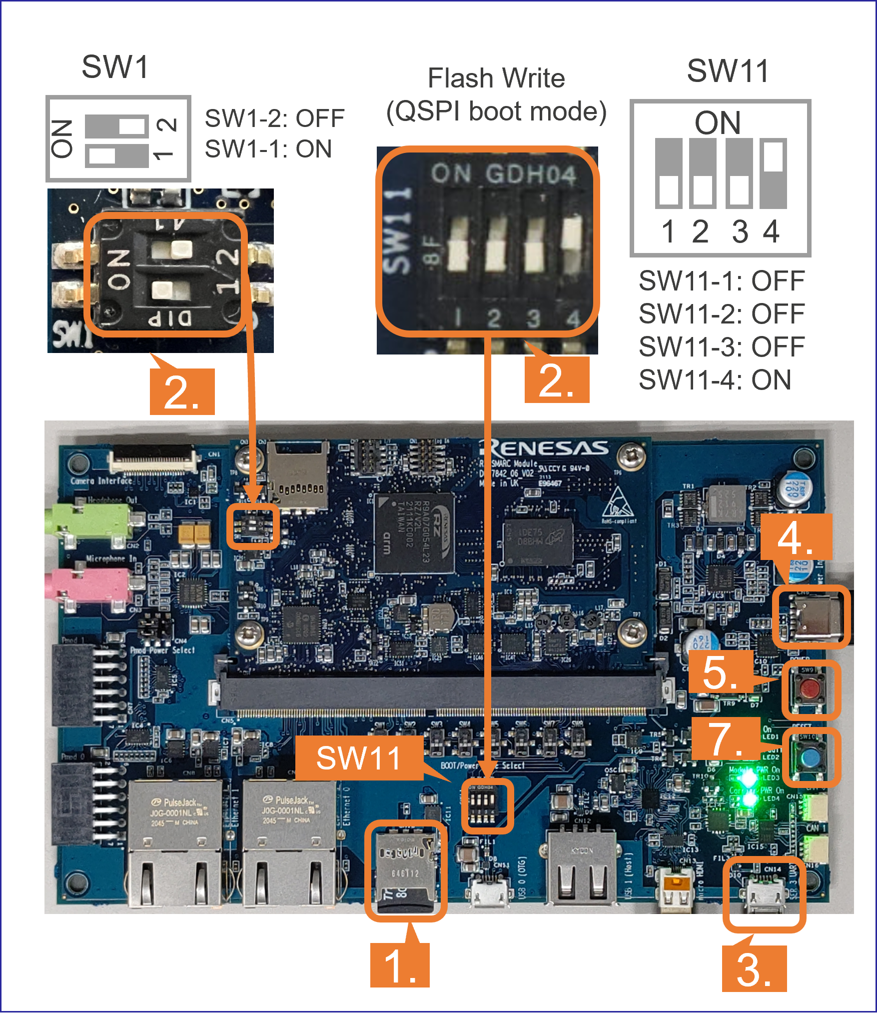
- Insert the microSD card to the Board.
Note Use the microSD card slot CN10 as shown in the figure.
- Change SW1 and SW11 setting as shown in the right figure.
- Connect the Board and Windows PC by the USB Serial to Micro USB cable.
- Connect the power cable to the Board.
- Press power button for 1 second to turn on the board.
- Open the terminal emulator, i.e., Tera Term, and connect with COMS port.
Note When using Tera Term, change the configuration as explained in Write bootloaders to QSPI on the board.
- On the terminal emulator, keep pressing ENTER key and on the board, press reset button.
- U-boot console will be activated.
- Run the following commands to set the booting configuration.
env default -a saveenv boot - After the boot-up, the login message will be shown on the console.
smarc-rzv2l login: - Log-in to the system using the information below.
- user:
root - password: none
- user:
- Shutdown the board to finish the U-boot setting.
Shutdown Procedures
- Insert the microSD card to the Board.
After this procedure, you can copy the AI Application and boot the board.
Refer to the Step 7: 2. Deploy Application to the Board in RZ/V2L EVK Getting Started.
D3. For RZ/V2H, RZ/V2N: How to boot from xSPI
This section explains how to boot from xSPI on RZ/V EVK.
Note
This instruction assumes that you have completed the steps in How to build RZ/V AI SDK Source Code and RZ/V EVK Getting Started.
However, if you would like to use the files for xSPI boot included in RZ/V AI SDK,
skip Step 3 of How to build RZ/V AI SDK Source code and use the files in
However, if you would like to use the files for xSPI boot included in RZ/V AI SDK,
skip Step 3 of How to build RZ/V AI SDK Source code and use the files in
${WORK}/board_setup/xSPI directory.| Device | How to build RZ/V AI SDK Source Code | RZ/V EVK Getting Started |
|---|---|---|
| RZ/V2H | Step 3 | Step 7-1 |
| RZ/V2N | Step 3 | Step 7-1 |
Note
To perform this procedure, please prepare the following equipment in addition to the 1.Necessary Equipments.
- Windows PC
- MicroUSB to Serial Cable for serial communication (Included in RZ/V EVK)
Follow the instruction below to setup the board.
-
1. Install Terminal Emulator
-
Install following software on Windows PC to be used as serial communication console.
-
Terminal emulator
- Operating Environment: Tera Term
-
Terminal emulator
-
Install following software on Windows PC to be used as serial communication console.
-
2. Install the serial port driver
Note If you have already installed the serial port driver, skip this step and proceed to next procedure.The serial communication between Windows PC and RZ/V EVK requires following driver.
https://ftdichip.com/drivers/vcp-drivers/
- Download the software "Virtual COM port (VCP) driver" from the windows version "setup executable" on the download page and extract it.
-
Run the
*.exefile extracted to install the serial port driver.
-
3. Write bootloaders on the board
- Copy following files to your Windows PC.
Device Path File name Description RZ/V2H ${YOCTO_WORK}/build/tmp/deploy/images/rzv2h-evk-ver1 Flash_Writer_SCIF_RZV2H_DEV_INTERNAL_MEMORY.mot
bl2_bp_spi-rzv2h-evk-ver1.srec
fip-rzv2h-evk-ver1.srecDirectory path and files when using files generated with How to build RZ/V AI SDK Source Code ${WORK}/board_setup/xSPI/bootloader Directory path and files when using files included with RZ/V AI SDK RZ/V2N ${YOCTO_WORK}/build/tmp/deploy/images/rzv2n-evk Flash_Writer_SCIF_RZV2N_DEV_LPDDR4X.mot
bl2_bp_spi-rzv2n-evk.srec
fip-rzv2n-evk.srecDirectory path and files when using files generated with How to build RZ/V AI SDK Source Code ${WORK}/board_setup/xSPI/bootloader Directory path and files when using files included with RZ/V AI SDK - Connect Windows PC and Board via Serial to MicroUSB Cable.
- Change DSW1 setting to Boot mode 3 (SCIF download). See the figure below.
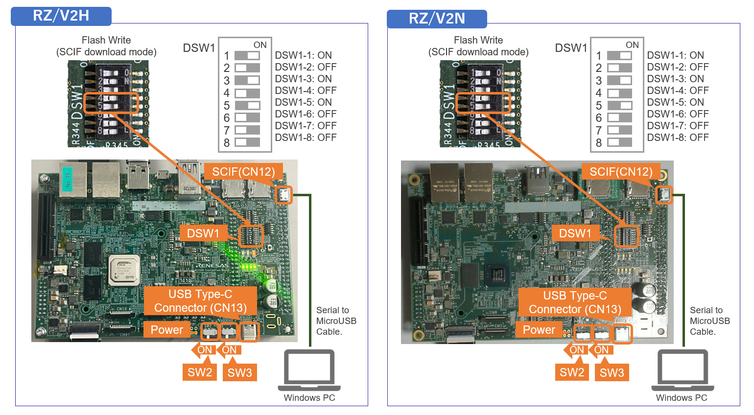
- Connect the power cable to CN13 on the Board.
- Turn the SW3 to ON.
- On Windows PC, open the terminal emulator. Here, we use Tera Term as an example.
- Select "File" > "New Connection" and select "Serial" port as shown below.
- Open the configuration window from the "Setup">"Terminal" and change the setting as follows.
Item Value New-line Receive: Auto Transmit: CR - Open the configuration window from the "Setup">"Serial port" and change the setting as follows.
Item Value Baud rate 115200 Data 8bit Parity none Stop 1bit Flow control none Transmit delay 0msec/char - Turn the SW2 to ON to power on the Board and following message will be displayed on the terminal.
SCI Download mode (Normal SCI boot) -- Load Program to SRAM --------------- -
Open "File" > "Send file..." and send the Flash Writer file (
*.mot) as a text.
If following message is displayed, the file transfer succeeded.Flash writer for RZ/V2x Series Vx.xx xxx.xx,20xx Product Code : RZ/V2x > - Enter "
XLS2" on the terminal to get following messages.> XLS2 ===== Qspi writing of RZ/V2x Board Command ============= Load Program to Spiflash Writes to any of SPI address. Program size & Qspi Save Address ===== Please Input Program Top Address ============ Please Input : H' - Enter "
8101e00". The log continues.Please Input : H'8101e00 ===== Please Input Qspi Save Address === Please Input : H' - Enter "
00000". The log continues.Please Input : H'00000 please send ! ('.' & CR stop load) - After the "please send!" message, open "File" > "Send file..." and send the
bl2_bp_spi-rzv2*.srecfile as a text from the terminal software. - In case a message to prompt to clear data like below, please enter "
y".SPI Data Clear(H'FF) Check : H'00000000-0000FFFF,Clear OK?(y/n) - Following log will be displayed. The end address is depending on the version of AI SDK.
Write to SPI Flash memory. ======= Qspi Save Information ================= SpiFlashMemory Stat Address : H'00000000 SpiFlashMemory End Address : H'00036D17 =========================================================== - Enter "
XLS2" on the terminal to get following messages.> XLS2 ===== Qspi writing of RZ/V2x Board Command ============= Load Program to Spiflash Writes to any of SPI address. Program size & Qspi Save Address ===== Please Input Program Top Address ============ Please Input : H' - Enter "
00000". The log continues.Please Input : H'00000 ===== Please Input Qspi Save Address === Please Input : H' - Enter "
60000". The log continues.Please Input : H'60000 please send ! ('.' & CR stop load) - After the "please send!" message, open "File" > "Send file..." and send the
fip-rzv2*.srecfile as a text from the terminal software. - In case a message to prompt to clear data like below, please enter "
y".SPI Data Clear(H'FF) Check : H'00000000-0000FFFF,Clear OK?(y/n) - Following log will be displayed. The end address is depending on the version of AI SDK.
Write to SPI Flash memory. ======= Qspi Save Information ================= SpiFlashMemory Stat Address : H'00060000 SpiFlashMemory End Address : H'0011C2EE =========================================================== - Power-off the board to change DSW1 for booting the board.
- Copy following files to your Windows PC.
-
4. Setup U-boot setting
Follow the procedure below to set the booting configuration of the board.
- Insert the microSD card to the Board.
Note Use the microSD card slot SD2 as shown in the figure.
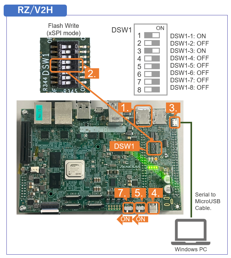
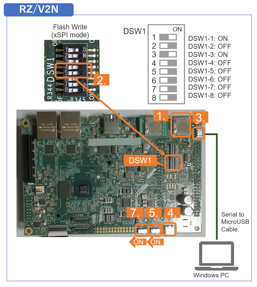
- Change DSW1 setting to Boot mode 2 (xSPI boot) as shown in the right figure.
- Connect the Board and Windows PC by the USB Serial to Micro USB cable.
- Connect the power cable to the Board.
- Turn the SW3 to ON.
- Open the terminal emulator, i.e., Tera Term, and connect with COMS port.
Note When using Tera Term, change the configuration as explained in Write bootloaders on the board.
- Turn the SW2 to ON to power on the Board.
- On the terminal emulator, keep pressing ENTER key.
- U-boot console will be activated.
- Run the following commands to set the booting configuration.
env default -a saveenv boot - After the boot-up, the login message will be shown on the console.
rzv2h-evk1 login: - Log-in to the system using the information below.
- user:
root - password: none
- user:
- Shutdown the board to finish the U-boot setting.
Shutdown Procedures
- Insert the microSD card to the Board.
This is the end of How to boot from xSPI on RZ/V2H EVK and RZ/V2N EVK.
D4. For RZ/V2N: How to boot from eMMC
This section explains how to boot from eMMC on RZ/V2N EVK.
Note
This instruction assumes that you have completed the steps in How to build RZ/V AI SDK Source Code and RZ/V EVK Getting Started below.
| Device | How to build RZ/V AI SDK Source Code | RZ/V EVK Getting Started |
|---|---|---|
| RZ/V2N | Step 3 | Step 7-1 |
Note
To perform this procedure, please prepare the following equipment in addition to the 1.Necessary Equipments.
- Windows PC
- MicroUSB to Serial Cable for serial communication (Included in RZ/V2N EVK)
- RZ/V2N EVK with eMMC sub board
For more information on connecting the sub board, see RZ/V2N Evaluation Board Kit Hardware Manual.
Follow the instruction below to setup the board.
-
1. Install Terminal Emulator
-
Install following software on Windows PC to be used as serial communication console.
-
Terminal emulator
- Operating Environment: Tera Term
-
Terminal emulator
-
Install following software on Windows PC to be used as serial communication console.
-
2. Install the serial port driver
Note If you have already installed the serial port driver, skip this step and proceed to next procedure.The serial communication between Windows PC and RZ/V EVK requires following driver.
https://ftdichip.com/drivers/vcp-drivers/
- Download the software "Virtual COM port (VCP) driver" from the windows version "setup executable" on the download page and extract it.
-
Run the
*.exefile extracted to install the serial port driver.
-
3. Write bootloaders on the board
- Writing the eMMC bootloader
- Copy following files to your Windows PC.
Device Path File name RZ/V2N ${YOCTO_WORK}/build/tmp/deploy/images/rzv2n-evk Flash_Writer_SCIF_RZV2N_DEV_LPDDR4X.mot
bl2_bp_mmc-rzv2n-evk.srec
bl2_bp_spi-rzv2n-evk.srec
fip-rzv2n-evk.srec
- Connect the eMMC sub board to the EVK and connect Windows PC and EVK CN12 connector via microB USB cable.
- Change DSW1 setting to Boot mode 3 (SCIF download). See the figure below.
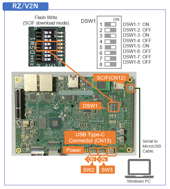
- Connect the power cable to CN13 on the Board.
- Turn the SW3 to ON.
- On Windows PC, open the terminal emulator. Here, we use Tera Term as an example.
- Select "File" > "New Connection" and select "Serial" port as shown below.
- Open the configuration window from the "Setup">"Terminal" and change the setting as follows.
Item Value New-line Receive: Auto Transmit: CR - Open the configuration window from the "Setup">"Serial port" and change the setting as follows.
Item Value Baud rate 115200 Data 8bit Parity none Stop 1bit Flow control none Transmit delay 0msec/char - Turn the SW2 to ON to power on the Board and following message will be displayed on the terminal.
SCI Download mode (Normal SCI boot) -- Load Program to SRAM --------------- -
Open "File" > "Send file..." and send the Flash Writer file (
*.mot) as a text.
If following message is displayed, the file transfer succeeded.Flash writer for RZ/V2x Series Vx.xx xxx.xx,20xx Product Code : RZ/V2x > - Enter "
EM_W" command and the following parameters in red.> EM_W EM_W Start ----------------------------------------------------------------------- Please select,eMMC Partition Area. 0:User Partition Area : 62160896 KBytes eMMC Sector Cnt : H'0 -H'0768FFFF 1:Boot Partition 1 : 32256 KBytes eMMC Sector Cnt : H'0 -H'0000FBFF 2:Boot Partition 2 : 32256 KBytes eMMC Sector Cnt : H'0 -H'0000FBFF --------------------------------------------------------- Select area(0-2)> 1 --Boot Partition 1 Program ----------------------------- Please Input Start Address in sector :1 Please Input Program Start Address : 8101E00 Work RAM (H'50000000-H'53FFFFFF) Clear.... please send ! ('.' & CR stop load) - After the "please send!" message, open "File" > "Send file..." and send the
bl2_bp_mmc-rzv2*.srecfile as a text from the terminal software. Following log will be displayed.please send ! ('.' & CR stop load) SAVE -FLASH....... EM_W Complete! - Enter "
EM_W" command and the following parameters in red.> EM_W EM_W Start ----------------------------------------------------------------------- Please select,eMMC Partition Area. 0:User Partition Area : 62160896 KBytes eMMC Sector Cnt : H'0 -H'0768FFFF 1:Boot Partition 1 : 32256 KBytes eMMC Sector Cnt : H'0 -H'0000FBFF 2:Boot Partition 2 : 32256 KBytes eMMC Sector Cnt : H'0 -H'0000FBFF --------------------------------------------------------- Select area(0-2)> 1 --Boot Partition 1 Program ----------------------------- Please Input Start Address in sector :300 Please Input Program Start Address : 0 Work RAM (H'50000000-H'53FFFFFF) Clear.... please send ! ('.' & CR stop load) - After the "please send!" message, open "File" > "Send file..." and send the
fip-rzv2*.srecfile as a text from the terminal software. Following log will be displayed.please send ! ('.' & CR stop load) SAVE -FLASH....... EM_W Complete! - Enter "
em_secsd" command and the following parameters in red.> em_secsd Please Input EXT_CSD Index(H'00 -H'1FF) :b1 EXT_CSD[B1] = 0x00 Please Input Value(H'00 -H'FF) :2 EXT_CSD[B1] = 0x02 > em_secsd Please Input EXT_CSD Index(H'00 -H'1FF) :b3 EXT_CSD[B3] = 0x01 Please Input Value(H'00 -H'FF) :8 EXT_CSD[B3] = 0x08 - Writing the xSPI bootloader
- Enter "
XLS2" command and the following parameters in red.> XLS2 ===== Qspi writing of RZ/G3S Board Command ============= Load Program to Spiflash Writes to any of SPI address. Micron : MT25QU512 Program Top Address & Qspi Save Address ===== Please Input Program Top Address ============ Please Input : H'8101E00 ===== Please Input Qspi Save Address === Please Input : H'0 please send ! ('.' & CR stop load) - After the "please send!" message, open "File" > "Send file..." and send the
bl2_bp_spi-rzv2*.srecfile as a text from the terminal software. - Following log will be displayed. The end address is depending on the version of AI SDK.
please send ! ('.' & CR stop load) Erase SPI Flash memory... Erase Completed Write to SPI Flash memory. ======= Qspi Save Information ================= SpiFlashMemory Stat Address : H'00000000 SpiFlashMemory End Address : H'00032BFF =========================================================== - Enter "
XLS2" command and the following parameters in red.> XLS2 ===== Qspi writing of RZ/G3S Board Command ============= Load Program to Spiflash Writes to any of SPI address. Micron : MT25QU512 Program Top Address & Qspi Save Address ===== Please Input Program Top Address ============ Please Input : H'0 ===== Please Input Qspi Save Address === Please Input : H'60000 please send ! ('.' & CR stop load) - After the "please send!" message, open "File" > "Send file..." and send the
fip-rzv2*.srecfile as a text from the terminal software.
Following log will be displayed. The end address is depending on the version of AI SDK.please send ! ('.' & CR stop load) Erase SPI Flash memory... Erase Completed Write to SPI Flash memory. ======= Qspi Save Information ================= SpiFlashMemory Stat Address : H'00060000 SpiFlashMemory End Address : H'0011B44E =========================================================== - Shutdown the board.
-
4. Formatting eMMC and writing file system to eMMC
Follow the procedure below to create a microSD card.
- Use the SD card created in Step 7-1:Setup RZ/V2N EVK in RZ/V2N EVK Getting Started.
- Insert the microSD card to your Linux PC and copy "core-image-weston-rzv2n-evk.tar.bz2" file on partition 2.
sudo mkdir /mnt/sd -p
sudo mount /dev/sdb2 /mnt/sd
sudo cp ${YOCTO_WORK}/build/tmp/deploy/images/rzv2n-evk/core-image-weston-rzv2n-evk.tar.bz2 /mnt/sd/home/root/
sync
sudo umount /mnt/sd
Warning Change/dev/sdbto your microSD card device name.
- Use the SD card created in Step 7-1:Setup RZ/V2N EVK in RZ/V2N EVK Getting Started.
-
5. Setup U-boot setting and writing rootfs to eMMC
Follow the procedure below to set the booting configuration of the board.
- Insert the microSD card to the Board.
Note Use the microSD card slot SD2 as shown in the figure.
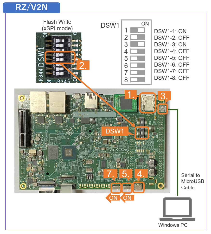
- Change DSW1 setting to Boot mode 2 (xSPI boot) as shown in the right figure.
- Connect the Board and Windows PC by the USB Serial to Micro USB cable.
- Connect the power cable to the Board.
- Turn the SW3 to ON.
- Open the terminal emulator, i.e., Tera Term, and connect with COMS port.
Note When using Tera Term, change the configuration as explained in Write bootloaders on the board.
- Turn the SW2 to ON to power on the Board.
- Log in as root and create partition the eMMC using the "
fdisk" command as shown below.root@rzv2n-evk:~# fdisk /dev/mmcblk0 Welcome to fdisk (util-linux 2.35.1). Changes will remain in memory only, until you decide to write them. Be careful before using the write command. Device does not contain a recognized partition table. Created a new DOS disklabel with disk identifier 0x7795745a. Command (m for help): o Created a new DOS disklabel with disk identifier 0x5ff48dd9. Command (m for help): n Partition type p primary (0 primary, 0 extended, 4 free) e extended (container for logical partitions) Select (default p):[Enter] Using default response p. Partition number (1-4, default 1):[Enter] First sector (2048-124321791, default 2048):[Enter] Last sector, +/-sectors or +/-size{K,M,G,T,P} (2048-124321791, default 124321791): +500M Created a new partition 1 of type 'Linux' and of size 500 MiB. Command (m for help): n Partition type p primary (1 primary, 0 extended, 3 free) e extended (container for logical partitions) Select (default p):[Enter] Using default response p. Partition number (2-4, default 2):[Enter] First sector (1026048-124321791, default 1026048):[Enter] Last sector, +/-sectors or +/-size{K,M,G,T,P} (1026048-124321791, default 124321791):[Enter] Created a new partition 2 of type 'Linux' and of size 58.8 GiB. Command (m for help): p Disk /dev/mmcblk0: 59.29 GiB, 63652757504 bytes, 124321792 sectors Units: sectors of 1 * 512 = 512 bytes Sector size (logical/physical): 512 bytes / 512 bytes I/O size (minimum/optimal): 512 bytes / 512 bytes Disklabel type: dos Disk identifier: 0x5ff48dd9 Device Boot Start End Sectors Size Id Type /dev/mmcblk0p1 2048 1026047 1024000 500M 83 Linux /dev/mmcblk0p2 1026048 124321791 123295744 58.8G 83 Linux Command (m for help): w The partition table has been altered. Calling ioctl() to re-read parti[ 189.289424] mmcblk0: p1 p2 tion table. Syncing disks. - Format the eMMC with "
mkfs.ext4" command as shown below.root@rzv2n-evk:~# mkfs.ext4 /dev/mmcblk0p1 mke2fs 1.45.7 (28-Jan-2021) Discarding device blocks: done Creating filesystem with 512000 1k blocks and 128016 inodes Filesystem UUID: 96fc4476-dd9f-49cc-8adf-78fefcd758ac Superblock backups stored on blocks: 8193, 24577, 40961, 57345, 73729, 204801, 221185, 401409 Allocating group tables: done Writing inode tables: done Creating journal (8192 blocks): done Writing superblocks and filesystem accounting information: done root@rzv2n-evk:~# mkfs.ext4 /dev/mmcblk0p2 mke2fs 1.45.7 (28-Jan-2021) Discarding device blocks: done Creating filesystem with 15411968 4k blocks and 3858432 inodes Filesystem UUID: 913c536d-da51-47a8-8baa-393f68ddc6aa Superblock backups stored on blocks: 32768, 98304, 163840, 229376, 294912, 819200, 884736, 1605632, 2654208, 4096000, 7962624, 11239424 Allocating group tables: done Writing inode tables: done Creating journal (65536 blocks): done Writing superblocks and filesystem accounting information: done - Write the Root filesystem as shown blow.
Note It will take a few minutes to write the Root filesystem.root@rzv2n-evk:~# mount /dev/mmcblk0p2 /mnt/ [ 357.263306] EXT4-fs (mmcblk0p2): mounted filesystem with ordered data mode. Opts: (null) root@rzv2n-evk:~# tar xf /home/root/core-image-weston-rzv2n-evk.tar.bz2 -C /mnt/ root@rzv2n-evk:~# sync root@rzv2n-evk:~# umount /dev/mmcblk0p2 - Shutdown the board and remove the microSD card.
Note To shutdown the board safely, please refer to A3. Shutdown RZ/V2H EVK and RZ/V2N EVK.
- Insert the microSD card to the Board.
-
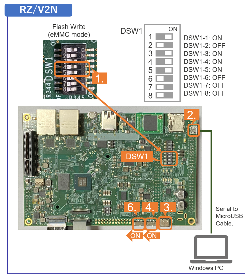
6. Booting from eMMC
Follow the procedure below to set the booting configuration of the board.
- Change DSW1 setting to Boot mode 1 (eMMC boot) as shown in the right figure.
- Connect the Board and Windows PC by the USB Serial to Micro USB cable.
- Connect the power cable to the Board.
- Turn the SW3 to ON.
- Open the terminal emulator, i.e., Tera Term, and connect with COMS port.
Note When using Tera Term, change the configuration as explained in Write bootloaders on the board.
- Turn the SW2 to ON to power on the Board.
- On the terminal emulator, keep pressing ENTER key.
- U-boot console will be activated.
- Run the following commands to set the booting configuration.
env default -a saveenv boot - After the boot-up, the login message will be shown on the console.
rzv2n-evk login: - Log-in to the system using the information below.
- user:
root - password: none
- user:
- Shutdown the board to finish the U-boot setting.
Note To shutdown the board safely, please refer to A3. Shutdown RZ/V2H EVK and RZ/V2N EVK.
This is the end of How to boot from eMMC on RZ/V2N EVK.