Renesas
RZ/V AI
The best solution for
starting your AI applications.
Provided by Renesas Electronics Corporation

To keep you updated,
Watch our GitHub repository
Watch
This project is maintained by renesas-rz
Hosted on GitHub Pages — Theme by orderedlist
This page explains how to start-up the AI SDK on the RZ/V2L Evaluation Board Kit.
Tutorial video is available here.
This tutorial is based on RZ/V2L AI SDK version 1.00.
Learn more about the RZ/V series.
Supported version: RZ/V2L AI SDK v1.00
Step 1: Obtain an evaluation board
Since MIPI camera module is included, you can start evaluating RZ/V2L immediately by building an environment.
Get RZ/V2L EVK
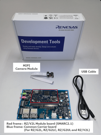
| Equipment | Details |
|---|---|
| RZ/V2L Evaluation Board | Evaluation board itself. |
| MIPI Camera Module | Google Coral Camera.Note that the CMOS sensor (OV5645) in the camera is no longer available, and should not be
used for mass production. |
| MicroUSB to Serial Cable | For serial communication between PC and the board. |
Step 2: Obtain necessary environment
1. Necessary Equipments
In addition to the RZ/V2L Evaluation Board Kit, please prepare the following equipments.
Note that Serial to MicroUSB Cable and MIPI Camera Module (Google Coral camera) is included in RZ/V2L Evaluation Board Kit.
| Equipment | Details |
|---|---|
| HDMI Monitor | Used to display the graphics |
| AC adapter | Power supply to the board |
| USB Cable Type-C | Connect AC adapter and the board |
| microSD card | Must have over 4GB capacity of blank space. Operating Environment: Transcend USH-I microSD 300S 16GB |
| Linux PC | Used for Setup microSD card and RZ/V2L AI SDK Setup. Operating Environment: Ubuntu 20.04 |
| SD card reader | Used for setting up microSD card |
| PC | Used for the serial communication console Operating Environment : Windows 10 |
| USB Hub | Optional. Used only when booting on HDMI monitor. |
| USB Keyboard | Optional. Used only when booting on HDMI monitor. |
| USB Mouse | Optional. Used only when booting on HDMI monitor. |
2. Necessary Software
Please prepare following software.
- Install following software on Ubuntu PC
- Docker
- git
- Install following software on PC to be used as serial communication console.
- Terminal emulator
- Operating Environment: Tera Term
- Operating Environment: Tera Term
- Terminal emulator
Step 3: Obtain RZ/V2L AI SDK
Download the RZ/V2L AI SDK from the link below.
Download Link
Check the Release Note included in the package.
Step 4: Extract RZ/V2L AI SDK package
This step explains how to extract the RZ/V2L AI SDK zip file.
- On your Linux PC, make the working directory.
mkdir -p ai_sdk_work - Register the working directory path to an environment variable.
export WORK=<path to the working directory>/ai_sdk_work - Move to the working directory.
cd ${WORK} - Extract RZ/V2L AI SDK zip file under the working directory.
unzip <Path to the file>/r11an0752ej*.zip -d ${WORK} - Check the working directory to confirm the package contents.
ls ${WORK}/- If the above command prints followings, the package is extracted correctly.
ai_sdk_setup board_setup documents references r11an0752ej*.pdf
- If the above command prints followings, the package is extracted correctly.
Step 5: Setup RZ/V2L AI SDK
This step explains how to setup the RZ/V2L AI SDK environment.
Note: Make sure that you have installed Docker on your Linux PC.
- On your Linux PC, move to the working directory.
cd ${WORK}/ai_sdk_setup - Build docker image.
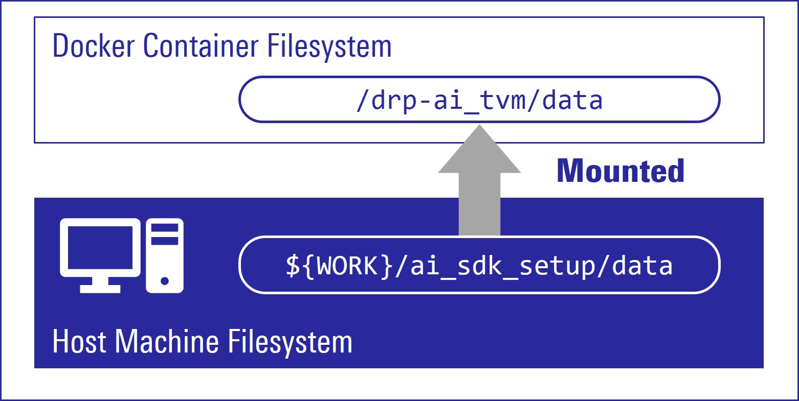
docker build -t rzv2l_ai_sdk_image --build-arg SDK="/opt/poky/3.1.17" --build-arg PRODUCT="V2L" . - Create new directory to be mounted on Docker container.
mkdir ${WORK}/ai_sdk_setup/data - Create docker container.
Here,rzv2l_ai_sdk_containeris a name of docker container, which can be changed by user.docker run -it --name rzv2l_ai_sdk_container -v $(pwd)/data:/drp-ai_tvm/data rzv2l_ai_sdk_imageThe local
$(pwd)/datais mounted to/drp-ai_tvm/dataon the Docker container by the above command option.
For example, you can use this directory to copy files created on the Docker container to your local environment.
- In docker container, run the following command to copy
libtvm_runtime.so, which is the necessary file for the board, to host machine.
cp /drp-ai_tvm/obj/build_runtime/V2L/libtvm_runtime.so /drp-ai_tvm/data - To exit docker, run following commands.
exit - To start the docker container
rzv2l_ai_sdk_containeragain, run the following command.
docker start -i rzv2l_ai_sdk_container
You have finished the RZ/V2L AI SDK environment setup.
You are ready to build the AI applications!
Step 6: Build RZ/V2L AI Application
This step explains how to build AI application.
AI Applications are provided in the GitHub repository.
To access the application, please see AI Applications.
Note:
The link in AI Applications page guides you to the latest GitHub repository.
Please be aware that latest AI Application requires latest AI SDK.
Application directory has the following structure.
| Directory | Details |
|---|---|
exe |
Execution environment required when running application on the board. |
src |
Application Source Code. |
| Other directory | Optional: Extra files that may be required other than above. |
Makefile |
Optional: Configuration to build the application. It may be included in the src directory. |
README.md |
Optional: Documentation of the application. |
Note: Following procedures are for users who would like to build the application from the source code.
If you would like to run the application as quickly as possible, you can skip to the next step since pre-build application binary is provided.
Building instructions.
In AI Applications, there are two types of applications.
- <Application 1>: Provided in RZ/V AI SDK GitHub repository.
- This repository provides the complete instruction in each application documentation.
- In this page, we use the Object Detection application from this repository for an example.
- <Application 2>: Provided in RZV2L_AiLibrary repository.
- This repository does not provide instructions for RZ/V2L AI SDK.
Option 1. For <Application 1>
Check the README.md document provided in application directory and follow the instruction in the chapter called “Application: Build Stage” (or similar) to build the application.
For example, in Object Detection application, follow the instruction in here to generate the following application binary.
-
object_detection
Note:
Thegit clonecommand shown in theREADME.mdwill download the latest source code and related files.
To download the files of AI Applications v1.00, please specify the version tag by adding-b v1.00when you running thegit clonecommand as shown below.git clone -b v1.00 https://github.com/renesas-rz/rzv_ai_sdk.git
After you generated the application binary, please proceed to Step 7
Option 2. For <Application 2>
Follow the instruction bellow to build the application.
- Run (or start) docker container.
For example, run the following command to start the docker container created in Step 5.
docker start -i rzv2l_ai_sdk_container - Change the environment variable to use the cross compiler.
Note: This command needs to be called everytime user opened the new terminal.
source /opt/poky/3.1.17/environment-setup-aarch64-poky-linux - Move to the mounted point in docker container.
cd /drp-ai_tvm/data - Download the application source code.
Here, we use RZV2L_AiLibrary repository Head Counter application as an example.
git clone https://github.com/Ignitarium-Renesas/RZV2L_AiLibraryNote: The command above will download the latest source code and related files.
To download the files of AI Applications v1.00, please specify the version tag by adding-b v1.00when you running thegit clonecommand as shown below.git clone -b v1.00 https://github.com/Ignitarium-Renesas/RZV2L_AiLibrary - Move to the application directory.
Note: The file configuration depends on each application. Please check the file configuration in the repository carefully.
cd RZV2L_AiLibrary/01_Head_count/Head_count_cam - Build the application with
makecommand.make - Check that following application is generated in the
RZV2L_AiLibrary/01_Head_count/.
Head_count_cam/exe- head_count_cam_app
- head_count_cam_app
- If you would like to build the other applications in Option 1, please exit and restart the docker container.
After you generated the application binary, please proceed to Step 7
Step 7: Setup RZ/V2L Evaluation Board Kit
This section explains how to setup the RZ/V2L Evaluation Board.
1. Install the serial port driver.
This step is only required for the first time.
Skip to the next step if you have already installed the serial port driver.
Click here to see the instructions.
The serial communication between Windows PC and RZ/V2L Evaluation Board Kit requires following driver.https://ftdichip.com/drivers/vcp-drivers/
1.1. Download the software "Virtual COM port (VCP) driver" from the windows version "setup executable" on the download page and extract it.
1.2. Run the
*.exe file extracted to install the serial port driver.1.3. Install the terminal emulator, i.e., Tera Term.
2. Write the bootloaders to the board.
Skip to the next step if you have already written the latest bootloaders to the board.
- Use the following files to write the bootloaders to the RZ/V2L Evaluation Board Kit according to Appendix: Write bootloaders.
Flash_Writer_SCIF_RZV2L_SMARC_
PMIC_DDR4_2GB_1PCS.motbl2_bp-smarc-rzv2l_pmic.srecfip-smarc-rzv2l_pmic.srec
3. Setup the SD card.
Skip to the next step if you have already setup the SD card with the latest Linux kernel, Linux device tree file and root filesystem.
microSD card contains the Linux kernel and root filesystem to boot-up the board.
You can use Linux PC to format the microSD card and expand the kernel and the root filesystem using SD card reader.
Following three files are necessary, which are placed on each partitions on microSD card.
They are in the ${WORK}/board_setup directory.
| File | Description | microSD card partition |
|---|---|---|
| Image-smarc-rzv2l.bin | Linux kernel image (The boot program) |
Partition 1 |
| Image-r9a07g054l2-smarc.dtb | Linux device tree file (The configuration file for booting) |
Partition 1 |
| core-image-weston-smarc-rzv2l.tar.bz2 | Linux Root filesystem | Partition 2 |
Follow the instruction below to prepare the microSD card.
Note: Here, we use "/dev/sdb" as microSD card device name.
- Create the following partitions on microSD card according to Appendix: Format SD card.
Partition Number Size Format 1 500MB (minimum 128MB) FAT32 2 All remaining Ext4 - Insert the microSD card to Linux PC.
- Check if the two partitions are created successfully by running
dfcommand.
Note: Device name of microSD card,
/dev/sdb, may differ depending on your environment.df -h Filesystem Size Used Avail Use % Mounted on … … … … … … /dev/sdb1 … … … … … /dev/sdb2 … … … … … - Run the following commands to setup the partition 1.
Note: Change
/dev/sdb, to your microSD card device name.sudo mkdir -p /mnt/sd sudo mount /dev/sdb1 /mnt/sd sudo cp $WORK/board_setup/Image-smarc-rzv2l.bin /mnt/sd sudo cp $WORK/board_setup/Image-r9a07g054l2-smarc.dtb /mnt/sd sync sudo umount /mnt/sd - Run the following commands to setup the partition 2, which is the root filesystem of the board.
Note: Change
/dev/sdb, to your microSD card device name.sudo mount /dev/sdb2 /mnt/sd sudo tar xfj $WORK/board_setup/core-image-weston-smarc-rzv2l.tar.bz2 -C /mnt/sd sudo cp $WORK/ai_sdk_setup/data/libtvm_runtime.so /mnt/sd/usr/lib64 sync sudo umount /mnt/sd - Eject the microSD card by running the following command and remove the microSD card from Linux PC.
sudo eject /dev/sdb
Step 8: Deploy the application to the Board
This section explains how to copy the application binary created in Step 6 to the board.
Users are expected to have finished the instructions in Setup the SD card in Step 7.
-
Insert the microSD card to Linux PC.
- Run the following command to mount the partition 2, which contains the root filesystem.
Note: Change
/dev/sdb, to your microSD card device name.sudo mount /dev/sdb2 /mnt/sd - Create the application directory on root filesystem.
Note: Directory name
tvmcan be determined by user.sudo mkdir /mnt/sd/home/root/tvm -
Copy the necessary files in execution environment.
Select the appropriate option below based on the application type explained in Building instructions in Step 6.
Option 1. <Application 1>
Check the
README.mddocument provided in application directory and follow the instruction in the chapter called “Application: Deploy Stage” (or similar) to deploy the application.For example, in Object Detection application, follow the instruction in here to find files to be copied.
Use the following command to copy the files to root filesystem.
sudo cp $WORK/ai_sdk_setup/data/<Path to target file>/<filename> /mnt/sd/home/root/tvmOption 2. <Application 2>
Run the following command to copy the whole repository to the root filesystem.
sudo cp $WORK/ai_sdk_setup/data/<Path to repository>/RZV2L_AiLibrary /mnt/sd/home/root/tvm -r - Run the following command to sync the data with memory.
sync - Run the following command to unmount the partition 2.
sudo umount /mnt/sd - Eject the microSD card by running the following command and remove the microSD card from Linux PC.
Note: Change
/dev/sdb, to your microSD card device name.sudo eject /dev/sdb
Step 9: Boot RZ/V2L Evaluation Board Kit
This section explains how to boot the RZ/V2L Evaluation Board Kit.
There are two types of booting options.
Option 1. Boot with Windows PC
You must use this option when booting the board for the first time.
This option uses Windows PC as a serial console.
Please see Appendix: Boot with PC to boot and set the booting configuration.
Option 2. Boot on HDMI monitor
Users can use this option after they set the booting configuration in Option 1.
This option does not require PC to control the serial console.
The instruction in the application documentation assumes this booting option.
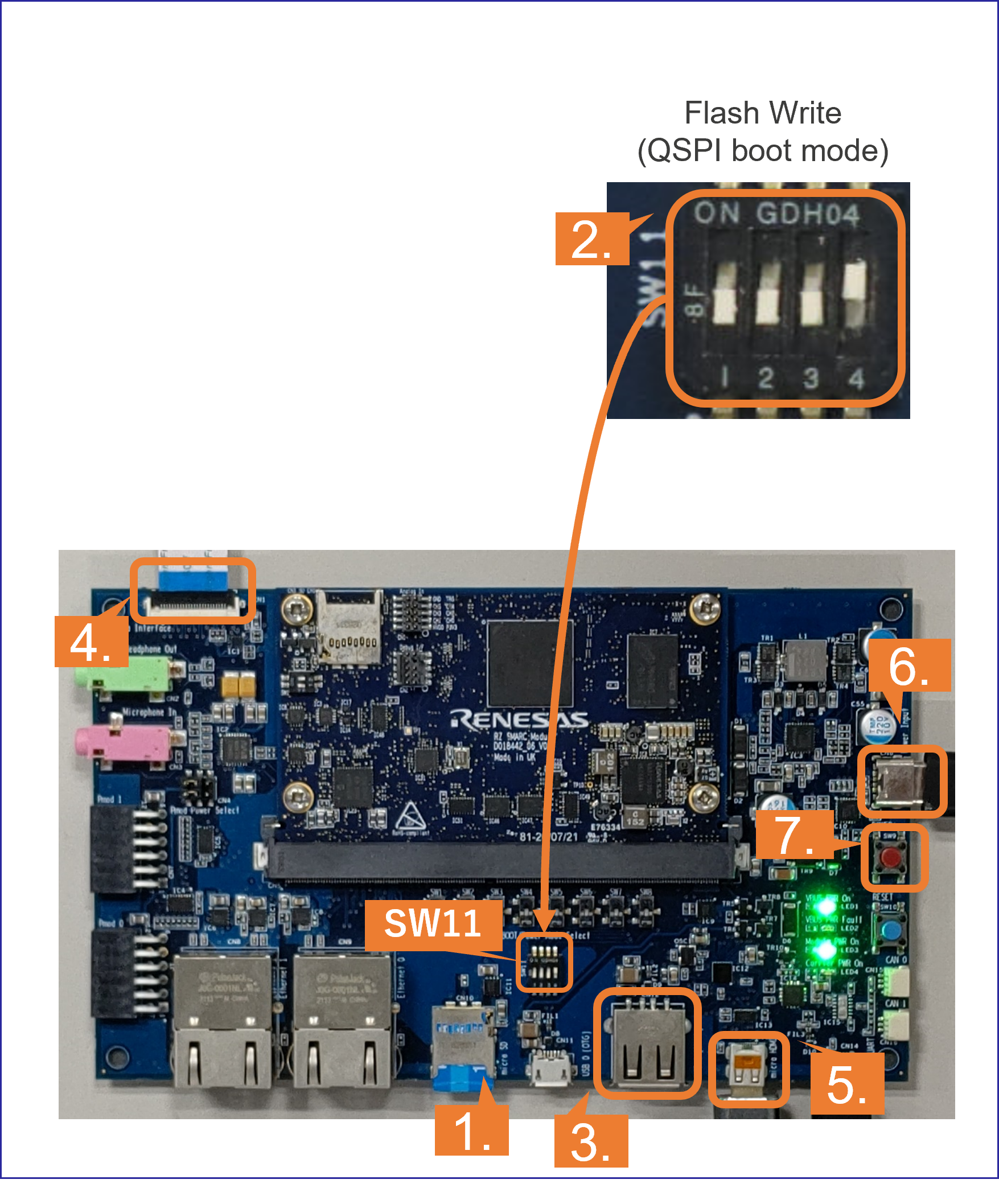
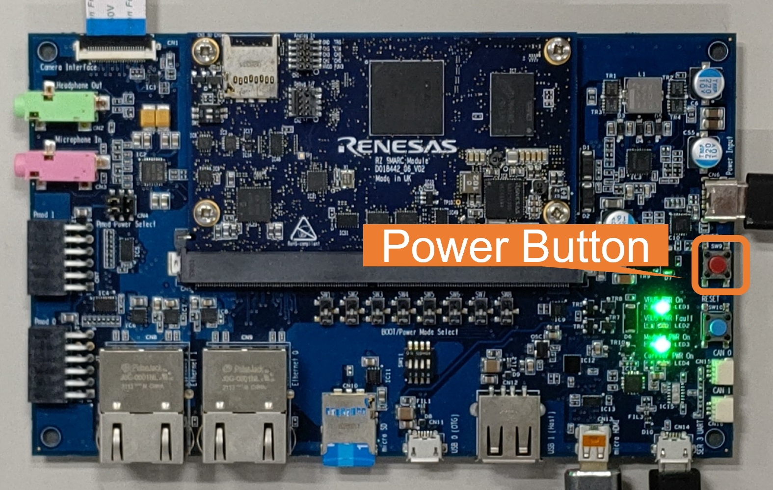
2. Change the SW11 setting as shown in the figure.
3. Connect the USB mouse and USB keyboard via USB hub.
4. Connect the Google Coral camera to the Board.
5. Connect the HDMI monitor to the Board.
6. Connect the power cable to the Board.
7. Press power button for 1 second to turn on the board.
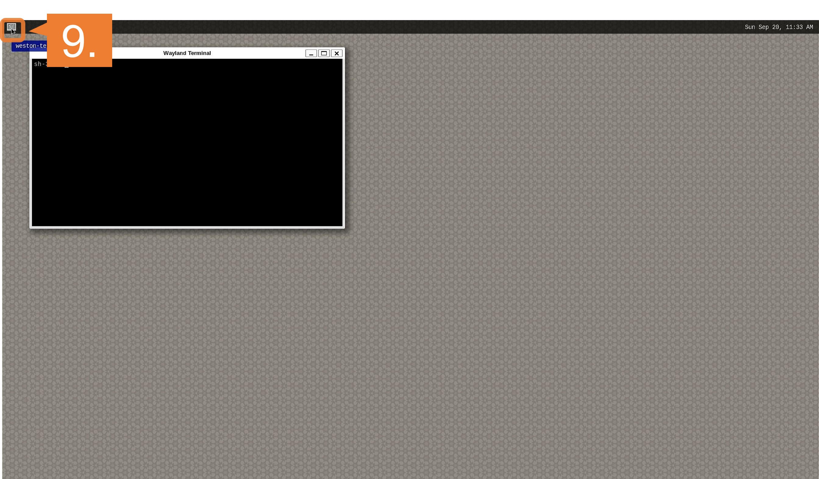
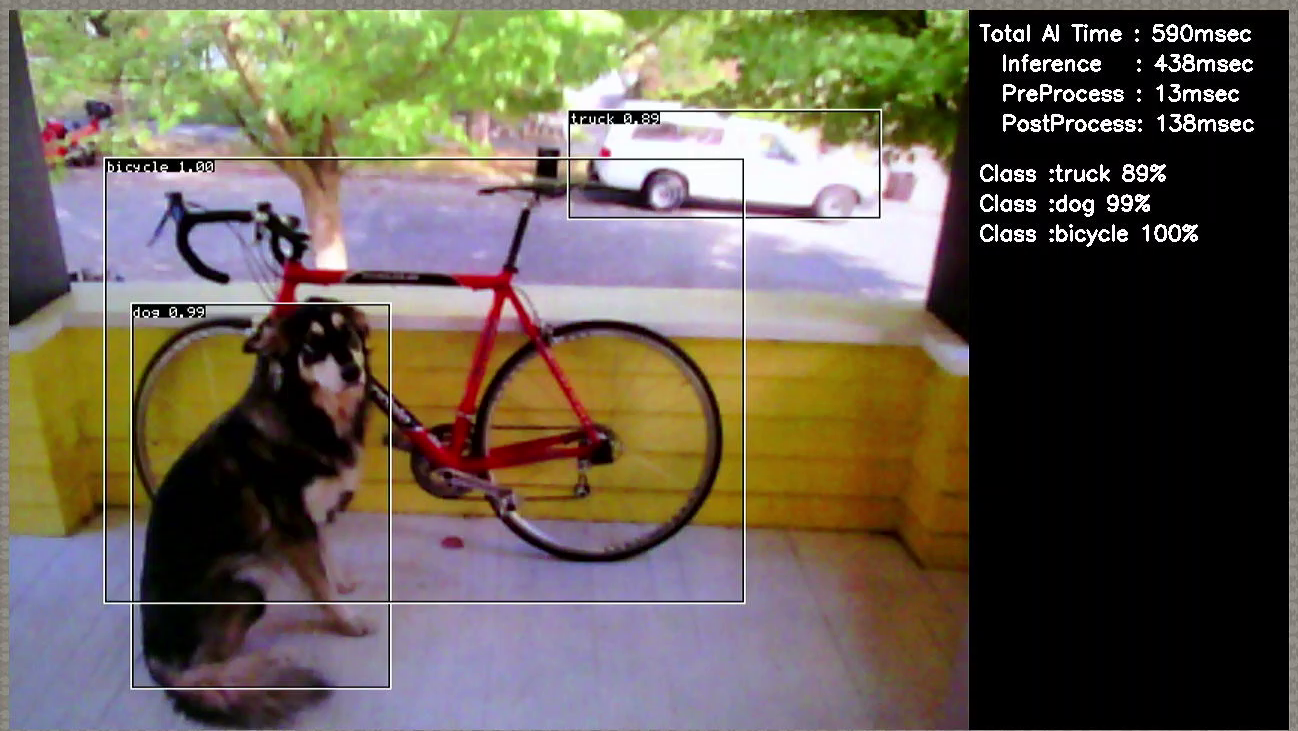
Step 10: Run the Application
Document of applications on GitHub has the instructions to run the application.
For example, in Object Detection application, follow the instruction in here to run the application.
If you have successfully run the application, you will see following window on HDMI screen.
Step 11: Shutdown the RZ/V2L Evaluation Board Kit
To power-off the RZ/V2L Evaluation Board Kit, follow the procedures below.
-
Run the
shutdowncommand on board console.shutdown -h now - On board console, check that shutdown procedure runs and ends with following log.
[xxxxx.xxxxxx] reboot: Power down -
Press and hold the power button for 2 seconds.
This is the end of Getting Started.
You have experienced the AI Application development procedures.
Next step is to change the application to create your own AI Application.
You can use the applications listed in AI Applications to expand your ideas!