Quick Start Guides
Notice
Please download RTK0EF0188Z78001ZJ_v17.0.0_prebuilt-images.zip package that includes the prebuilt images.
RTK0EF0188Z78001ZJ_v17.0.0_prebuilt-images.zip
To boot Android, it’s required to flash Android bootloader and flash Android images.
Device connection information:
| Peripheral | SMARC RZ/G3L |
|---|---|
| HDMI | Mirco HDMI (HDMI) |
| USB cable for HDMI touch panel | USB 2.0 Type A Port (USB1B-1A_HOST) |
| USB cable for serial console | USB debug serial (SER3_UART) |
| USB cable for adb | Micro USB 2.0 (USB0_OTG) |
| Ethernet cable | Ethernet port 0 (ETH0), Ethernet port 1 (ETH1) |
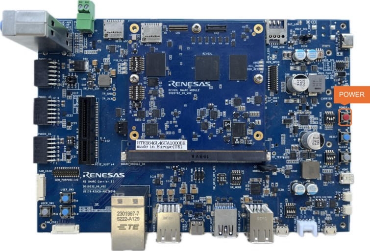
Start up the device by pressing and hold the Power button (POWER) for 2 seconds.
Caution
It's NOT recommended to hot plug HDMI. It may cause board broken.
Note
- It's required to disable "Auto Select" feature on monitor to disable auto scanning input.
The standard configuration is shown in the following figure.
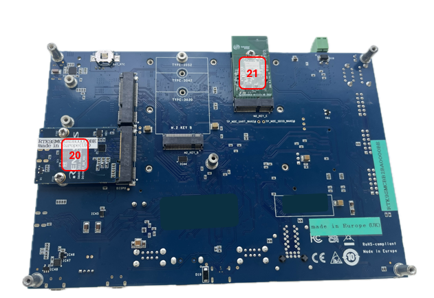 Figure. Bottom side view of the SMARC RZ/G3L main board
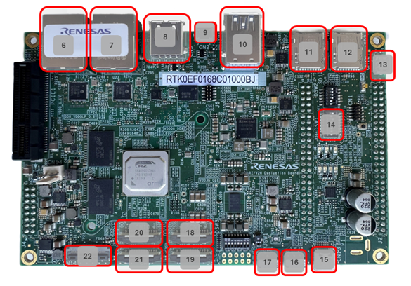 Figure. Top side view of the SMARC RZ/G3L main board
| Number | Description |
|---|---|
| 1 | Power input (USB-C_PWR_IN) |
| 2 | Power button (POWER) |
| 3 | Reset button (RESET) |
| 4 | Sleep button (SLEEP) |
| 5 | USB debug serial (SER3_UART) |
| 6 | Micro USB 2.0 (USB0_OTG) |
| 7 | USB 2.0 Type-A (USB1B-1A_HOST) |
| 8 | Ethernet port (ETH1) and (ETH0) |
| 9 | MIPI-CSI2 connector (CAM_CSI1) |
| 10 | Android POWER Button |
| 11 | Volume Down Button |
| 12 | Volume Up Button |
| 13 | AUX/Headphone/MIC connector (AUDIO) |
| 14 | Micro SDCard slot (SDI0) |
| 15 | BOOT MODE (SW_MODE) |
| 16 | SW_OPT_MUX |
| 17 | eSD (uSD0) |
| 18 | LED (DDR_RET) |
| 19 | RZ SMARC Breakout (CN1) |
| 20 | Micro HDMI (HDMI) |
| 21 | Wi-Fi (2AE / 2BC M.2 Module) |
Flashing AOSP image
Flashing bootloader
It’s needed to update the firmware (*). Especially, it’s mandatory to use U-Boot which support “fastboot” command.
(*)bootloader binaries:
- bl2_bp_smarc_rzg3l_emmc.bin
- bl2_bp_smarc_rzg3l_emmc.srec
- bl2_bp_smarc_rzg3l_esd.bin
- bl2_bp_smarc_rzg3l_esd.srec
- fip_smarc_rzg3l.bin
- fip_smarc_rzg3l.srec
Use provided *.mot (Flash Writer) firmware below for flashing eMMC bootloader:
- Flash_Writer_SCIF_RZG3L_SMARC_LPDDR4.mot
Use provided *.ttl (TeraTerm Language) macros below for flashing eMMC bootloader:
- emmc_flash_rzg3l.ttl
Use provided script below for flashing eSD bootloader:
- flash_eSD_smarc_rzg3l.sh
Note
- The command in the box below will be executed on the Ubuntu Host PC.
- In SMARC RZ/G3L, eMMC and eSD boot mode are supported.
- For RZ/G3L prebuilt images
- Confirm the content of
RTK0EF0188Z78001ZJ_v17.0.0_prebuilt-images
Content of the
RTK0EF0188Z78001ZJ_v17.0.0_prebuilt-imagesConfirm the content of prebuilt-images
Content of the
RTK0EF0188Z78001ZJ_v17.0.0_prebuilt-images/prebuilt-images|-- adb |-- bl2_bp_smarc_rzg3l_emmc.bin |-- bl2_bp_smarc_rzg3l_emmc.srec |-- bl2_bp_smarc_rzg3l_esd.bin |-- bl2_bp_smarc_rzg3l_esd.srec |-- boot.img |-- dtb.img |-- dtbo.img |-- fastboot |-- fastboot.sh |-- fastboot_functions.sh |-- fip_smarc_rzg3l.bin |-- fip_smarc_rzg3l.srec |-- init_boot.img |-- mke2fs |-- super.img |-- vbmeta.img |-- vendor_boot.img |-- flash_eSD_smarc_rzg3l.sh |-- Flash_Writer_SCIF_RZG3L_SMARC_LPDDR4.mot `-- emmc_flash_rzg3l.ttl
Please follow the steps below to flash IPL (these steps are executed on Windows PC and use TeraTerm tool for flashing) on RZ/G3L boards.
Set SW_MODE to SCIF Download Mode:
Switch Name Pin1 Pin2 Pin3 Pin4 SW_MODE OFF ON OFF ON Connect SER3_UART to Windows PC (via micro-USB cable), plug power adapter into Power Input (POWER). Run TeraTerm on Windows PC, choose correct COM port and change its Baud rate to 115200 (“Setup > Serial port...”).
On TeraTerm, choose “File > Disconnect” (if any), then “File > New connection…”. Press and hold the Power button (POWER) for 2 seconds to start up board and you will receive messages below:
Copy below files to the same folder on firmware Windows machine
- All “*.mot” files
- All “*.ttl” files
- All “*.srec” files
Note
Make sure to copy them to the same directory.
On TeraTerm, go to “Control > Macro”, choose corrected ttl file:
“emmc_flash_rzg3l.ttl”
TeraTerm will automatically load firmware, then detect all “*.srec” files and load them to appropriate addresses.After loading finished, the output looks like:
Press and hold the Power button (POWER) for 2 seconds to turn off board and plug out Power input
Set SW_MODE to eMMC boot mode:
Switch Name Pin1 Pin2 Pin3 Pin4 SW_MODE ON OFF OFF ON Plug in Power input again. Press and hold the Power button (POWER) for 2 seconds to turn on board again! On Teraterm choose “File > Disconnect”, “File > New connection…”. After this step, if you see the similar messages as yellow box below, it means that bootloader is loaded successfully.
NOTICE:  BL2: v2.10.5(release):ed630410f
NOTICE:  BL2: Built : 10:28:43, Aug 10 2026
NOTICE:  eMMC boot from partition 1
NOTICE:  BL2: SYS_LSI_MODE: 0x13051
NOTICE:  BL2: SYS_LSI_DEVID: 0x87d9447
NOTICE:  eMMC boot from partition 1
NOTICE:  Load dst=0x42540 src=(p:1)0x60000(768) len=0x10(1)
NOTICE:  eMMC boot from partition 1
NOTICE:  Load dst=0x426d8 src=(p:1)0x60010(768) len=0x28(1)
NOTICE:  eMMC boot from partition 1
NOTICE:  Load dst=0x44000000 src=(p:1)0x60090(768) len=0x3e000(497)
NOTICE:  eMMC boot from partition 1
NOTICE:  Load dst=0x42540 src=(p:1)0x60000(768) len=0x10(1)
NOTICE:  eMMC boot from partition 1
NOTICE:  Load dst=0x426d8 src=(p:1)0x60010(768) len=0x28(1)
NOTICE:  Load dst=0x426d8 src=(p:1)0x60038(768) len=0x28(1)
NOTICE:  eMMC boot from partition 1
NOTICE:  Load dst=0x50000000 src=(p:1)0x9e090(1264) len=0xd5440(1707)
NOTICE:  BL2: Booting BL31
NOTICE:  BL31: v2.10.5(release):ed630410f
NOTICE:  BL31: Built : 10:28:46, Aug 10 2026


U-Boot 2024.07-gabd6dbbbe3 (Aug 10 2026 - 10:28:33 +0700)

CPU:   Renesas Electronics CPU rev 16.15
Model: smarc-rzg3l
DRAM:  1.9 GiB
Core:  28 devices, 16 uclasses, devicetree: separate
MMC:   sd@11c00000: 0, sd@11c10000: 1
Loading Environment from MMC... Reading from MMC(0)... OK
In:    serial@100ac000
Out:   serial@100ac000
Err:   serial@100ac000
Net:
Error: ethernet@11c40000 No valid MAC address found.

Error: ethernet@11c30000 No valid MAC address found.

Error: ethernet@11c30000 No valid MAC address found.

Error: ethernet@11c40000 No valid MAC address found.
No ethernet found.

Hit any key to stop autoboot:  0
CAUTION
- This step is only for loading bootloaders. Users still need to flash Android images to boot Android.
Note
- After first flashing eMMC bootloaders of this release, users can use fastboot to update eMMC bootloaders.
- U-boot environment variables will be erased after updating bootloaders by fastboot (fastboot.sh). Please back up before updating.
Note
To run update eMMC bootloaders properly, It's required to set 'platform' variable to r9a08g046 via command in u-boot console
- To be in fastboot mode, please execute below command in u-boot console:
- On Ubuntu host PC, execute command:
<serial#> is board serial number which is set in Flashing images using fastboot.
Plug SDCard into the host PC.
Copy the files below to the same folder on host PC:
- bl2_bp_smarc_rzg3l_esd.bin
- fip_smarc_rzg3l.bin
flash_eSD_smarc_rzg3l.sh
On Ubuntu Host PC, execute command:
Example: ./flash_eSD_smarc_rzg3l.sh/dev/sdf (sdf is block device. It should not have partition number)CAUTION
This script will format the SD card, so back up your data before proceeding
Set SW_MODE to eSD boot mode:
Switch Name Pin1 Pin2 Pin3 Pin4 SW_MODE ON ON OFF ON Plug SDCard to uSD0 on RZ/G3L SMARC SOM board, press Reset button (RESET) to boot the board
Expected eSD boot mode logs:
NOTICE:  BL2: v2.10.5(release):ed630410f
NOTICE:  BL2: Built : 08:47:57, Aug  5 2026
NOTICE:  SD boot from partition 0
NOTICE:  BL2: SYS_LSI_MODE: 0x13001
NOTICE:  BL2: SYS_LSI_DEVID: 0x87d9447
NOTICE:  SD boot from partition 0
NOTICE:  Load dst=0x42540 src=(p:0)0x60000(768) len=0x10(1)
NOTICE:  SD boot from partition 0
NOTICE:  Load dst=0x426d8 src=(p:0)0x60010(768) len=0x28(1)
NOTICE:  SD boot from partition 0
NOTICE:  Load dst=0x44000000 src=(p:0)0x60090(768) len=0x3e000(497)
NOTICE:  SD boot from partition 0
NOTICE:  Load dst=0x42540 src=(p:0)0x60000(768) len=0x10(1)
NOTICE:  SD boot from partition 0
NOTICE:  Load dst=0x426d8 src=(p:0)0x60010(768) len=0x28(1)
NOTICE:  Load dst=0x426d8 src=(p:0)0x60038(768) len=0x28(1)
NOTICE:  SD boot from partition 0
NOTICE:  Load dst=0x50000000 src=(p:0)0x9e090(1264) len=0xd5440(1707)
NOTICE:  BL2: Booting BL31
NOTICE:  BL31: v2.10.5(release):ed630410f
NOTICE:  BL31: Built : 08:48:01, Aug  5 2026


U-Boot 2024.07-gabd6dbbbe3 (Aug 05 2026 - 08:46:59 +0700)

CPU:   Renesas Electronics CPU rev 16.13
Model: smarc-rzg3l
DRAM:  1.9 GiB
Core:  28 devices, 16 uclasses, devicetree: separate
MMC:   sd@11c00000: 0, sd@11c10000: 1
Loading Environment from MMC... Reading from MMC(0)... *** Warning - bad CRC, using default environment

Use boot device: mmc 0 (eMMC/eSD)
himport_r: can't insert "boot_device=-1" into hash table
Use boot device: mmc 0 (eMMC/eSD)
In:    serial@100ac000
Out:   serial@100ac000
Err:   serial@100ac000
Net:
Error: ethernet@11c40000 No valid MAC address found.

Error: ethernet@11c30000 No valid MAC address found.

Error: ethernet@11c30000 No valid MAC address found.

Error: ethernet@11c40000 No valid MAC address found.
No ethernet found.

Hit any key to stop autoboot:  0
CAUTION
- This step is only for loading bootloaders. Users still need to flash Android images refer to Flashing images using fastboot.
Note
- After first flashing eSD bootloaders of this release, users do NOT need to use flash_eSD_smarc_rzg3l.sh to update bootloaders. Users can use fastboot to update eSD bootloaders.
- U-boot environment variables will be erased after updating bootloaders by fastboot (fastboot.sh). Please back up before updating.
Note
To run update eSD bootloaders properly, It's required to set 'platform' variable to r9a08g046 via command in u-boot console
- To be in fastboot mode, please execute below command in u-boot console:
- On Ubuntu host PC, execute command:
<serial#> is board serial number which is set in Flashing images using fastboot.
Flashing images using fastboot
This step should be done after successful IPL and U-Boot flashing. (See Flashing bootloader)
Note
When users load bootloader at the first time, bootloaders will display warning messages as below:
This warning is expected. The "misc" partition doesn't exist yet because no Android images have been flashed. It will be created automatically during the Android image flashing steps.
1) Using “fastboot usb”, please connect USB0_OTG to Ubuntu Host PC with an USB cable for fastboot.
2) Power on device and interrupt autoboot.
3) Execute below commands on target board.
Set environment values on U-boot
env default -a
setenv serial# <serial number>  # Set board serial number to serial#: 0000XXXX (where XXXX = board number like 0011)
editenv bootargs
Edit bootargs: video=XXXX-X:d
“video” variable needs to set parameter related to display configuration.
video=HDMI-A-1:e (Skip hotplug, keep connector always on)
4) Execute below commands on Ubuntu Host PC.
Format eMMC/SD card partition and write image file to target. Please use “fastboot” command that you built in step Building Android, IPL, U-Boot, and Kernel sources. (Of course, fastboot tool included in latest Android SDK is also worked.)
Method: Fastboot USB
- Following below commands to flash Android images:
cd <your working dir>/RTK0EF0188Z78001ZJ_v17.0.0_prebuilt-images/prebuilt-images
chmod a+x *
sudo ./fastboot -s <serial#> oem format # Expected output: "Finished. Total time: x.xxxs"
sudo ./fastboot -s <serial#> reboot bootloader # Expected output: "Finished. Total time: x.xxxs"
sudo ./fastboot.sh --serial=<serial#> --noresetenv --nobl # Expected output: "SUCCESS. Script finished successfully"
Note
- HDMI is required to boot successfully.
- It is required to plug external power if user uses external devices like portable monitor, USB hub, etc.
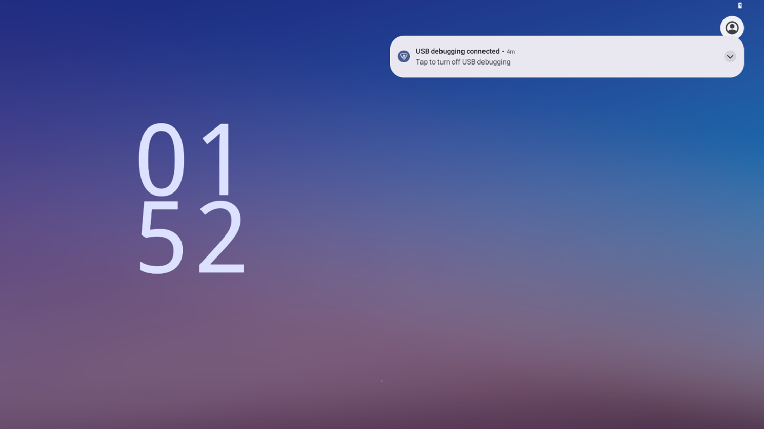
Once the boot process completes successfully, the GUI should appear on the HDMI monitor.
The console should display logs like the following:
Booting SMARC RZ/G3L
Note
To boot the Android on RZ/G3L, it's required to flash Bootloaders and flash Android images according to the Quick Start Guides
Please follow below steps to boot Android on SMARC RZ/G3L:
- Change SW_MODE setting to eMMC boot mode.
- Connect Micro USB 2.0 (USB0_OTG) to Ubuntu Host PC with USB cable.
- Connect the HDMI touch panel to the Board.
Note: HDMI monitor can also be used.
- Connect the USB cable for HDMI touch panel to the USB 2.0 Type A (USB1B-1A_HOST).
Note: USB mouse can also be used.
Connect the power cable to the board, press and hold the Power button (POWER) for 2 seconds.
Verify that the following is displayed on the HDMI screen.
Note
- Devices with #AC0 or #BC0 in the part number, as well as RZ/G3L EVKIT with Lot # 0000308367 –0000309059 that incorporate these devices, have limitations in the MIPI DSI feature.
- For details, please contact a Renesas Electronics sales representative.
Enable and Run Sample Applications
This section explains how to enable and run the Sample Applications.
Enable Sample Applications
Enable demo applications with environment variable
- Step 1: Set the demo support environment variable:
- Step 2: Re-build the Android image following the instructions in Building Android, IPL, U-Boot, and Kernel sources
Run the Application
This section explains how to run the Application.
Note
- Connect the HDMI touch panel with USB. If you do not have one, you can substitute it with a HDMI display and a USB mouse connected to SMARC RZ/G3L.
Step 1: Boot Android Environment
Confirm if Android environment is booted successfully, the following screen is displayed:
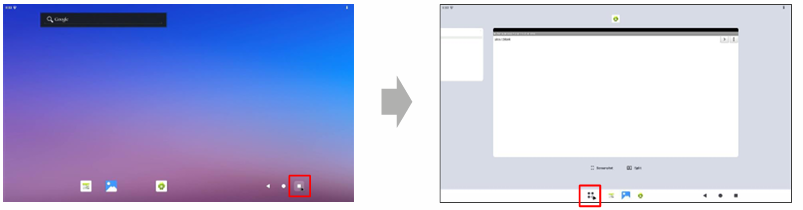
After Booting SMARC RZ/G3L, the following screen will appear after a few minutes.Swipe up to open the home screen, When the home screen appears, swipe up to get UI of list of application.
Step 2: Run the Application
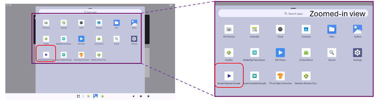
Simple Playback Sample App
Prepare media (video) via "adb push"
Click to Simple Playback Sample App icon to start the application
The application screen will appear. Swipe up to show all videos
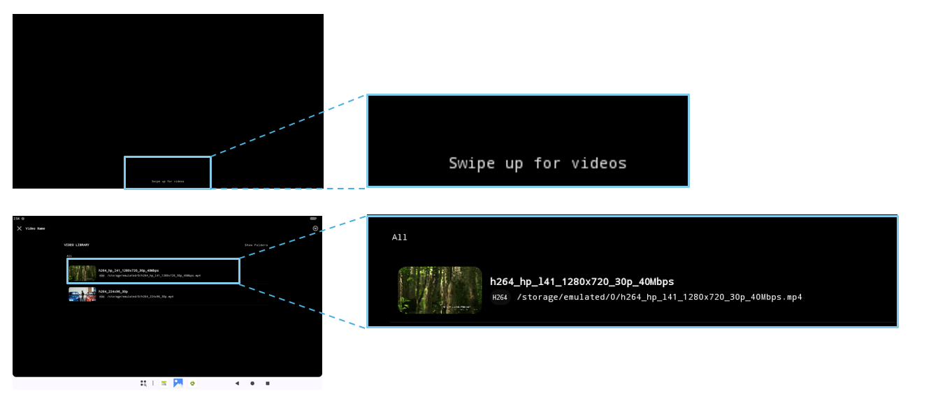
Choose a video to play.
Note
- Can not detect media files when use adb shell command to push video from host machine to device. (Workaround: Reboot the device).
- After playback video at the end, the app stops at last frame instead of back to main screen.
Grafika
Click to Grafika App icon to start the application
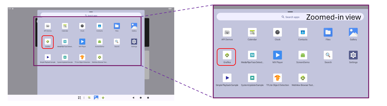
The application screen will appear the list of grafika test cases
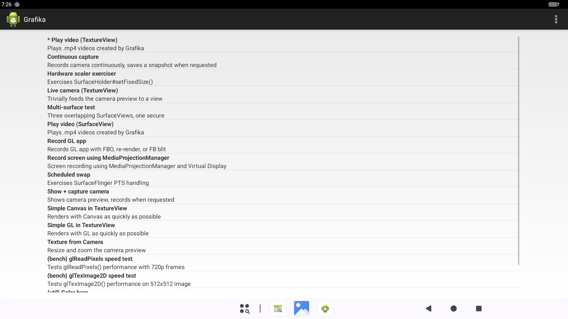
Choose a testcase to test.
Note
Demo/Grafika fails for Play video (TextureView) and Play video (SurfaceView): gen-slider.mp4 --> Crash application (Grafika keep stopping)
Step 3: Close the Application
To exit the application, tap the square icon at the bottom-right of the screen. When the screen shown below is displayed, swipe the application to the right. The CLEAR ALL button will appear on the left side of the screen. Tap this button. The application will close and return to the home screen.
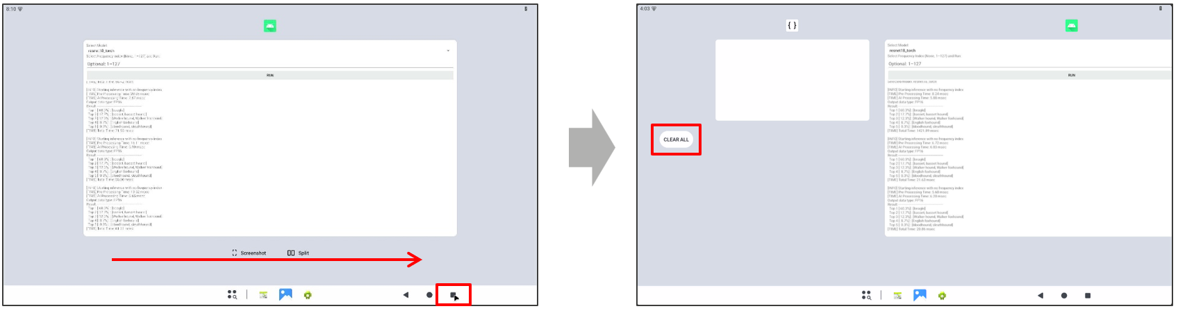
Note
If you are using a touch panel, you can also close the application by flicking it up.
Current Measurement Program
The Current Measurement Program for the RZ/G series supports current and voltage monitoring, graph plotting, and data logging. The program is not officially supported on the SMARC RZ/G3L, but it is expected to operate correctly because the platform uses the same current-sensing hardware as the supported platforms.
Please reference detail at: https://www.renesas.com/en/document/apn/rz-series-current-measurement-program
In this section, the Current Measurement Program is used to measure current and voltage, plot graphs, and save data while the system is operating in S2R (Suspend-to-RAM) mode. This demonstrates the power-saving benefits of S2R mode.
How to use Current Measurement Program
Step 1: Power off the board and connect USB cables as shown below:
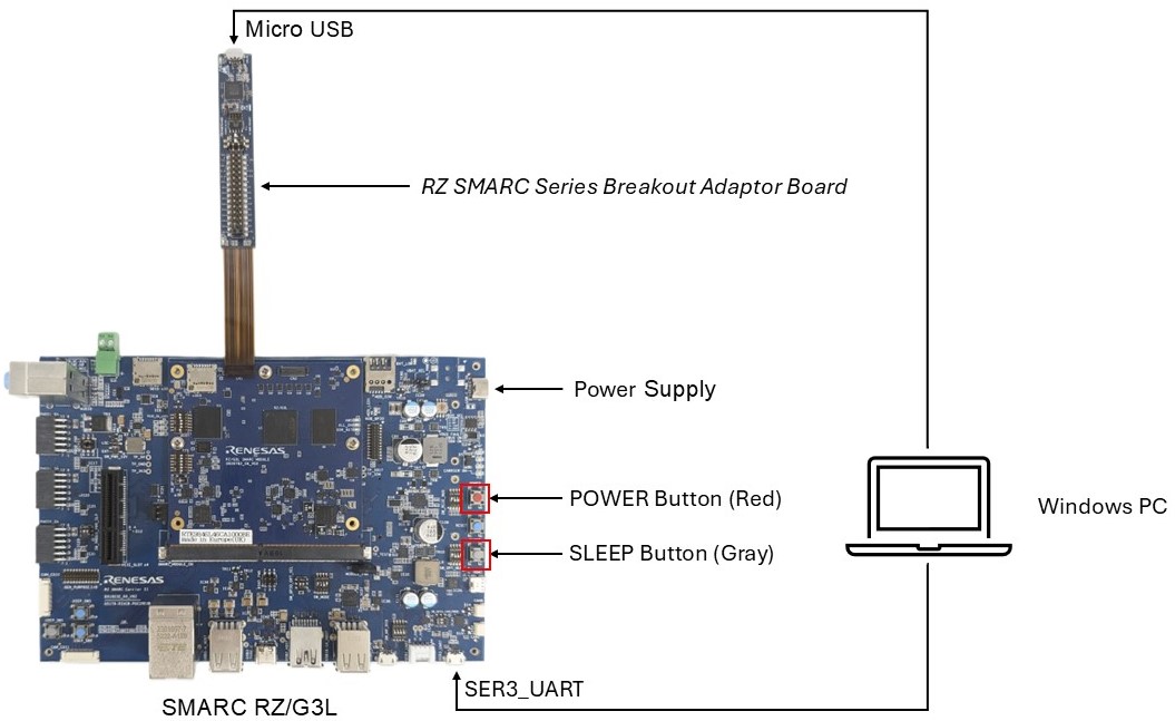
Figure. SMARC RZG3L connection to Current measurement
Note
When SER3_UART is connected to a Windows PC, run TeraTerm on the PC, select the correct COM port and change its Baud rate to 115200 (“Setup > Serial port…”).
Step 2: Set up the Current Meansurement application on the Windows PC.
a. Log in to Renesas website and download the Current Meansurement package from the link below: https://www.renesas.com/en/document/swe/rz-series-current-measurement-program
b. Extract the ZIP file twice and confirm that the extracted files match those shown below:
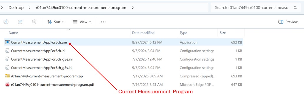
Figure. Current Measurement Program executable files
c. Double click on CurrentMeasurementAppFor5ch.exe to start the program. Since the SMARC RZ/G3L supports only four channels, make sure to uncheck the 0x9E I2C address.
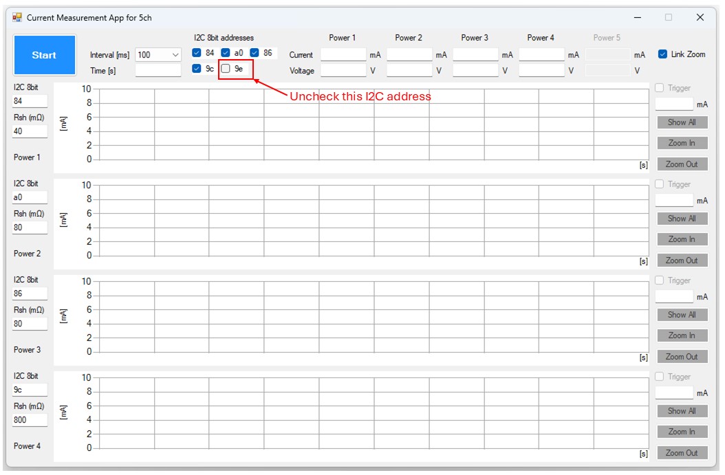
Figure. Current Measurement Program with 0x9E I2C address unchecked
d. Click the "Start/Stop" Button to start or stop measurement.

Figure. Start or Stop measurement
Step 3: Press the POWER button to boot Android.
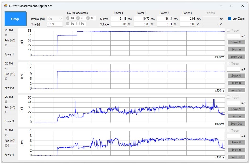
Figure. Current and voltage measurements during Android boot
Step 4: Wait for Android to finish booting, then open API Demos -> Graphics -> OpenGL ES -> Kube to run a graphics workload.
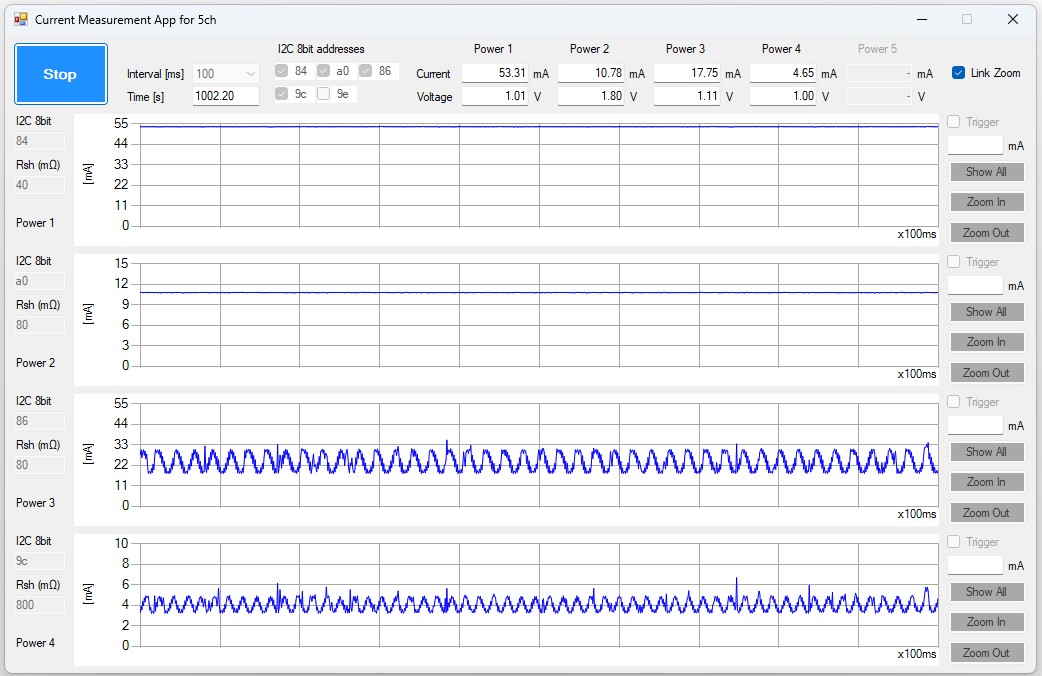
Figure. Voltage and current measurements while running API Demos
Step 5: Run the following commands on the board console to enter Suspend-to-RAM mode:
su
echo 0 > /sys/module/printk/parameters/console_suspend
echo deep > /sys/power/mem_sleep
echo enabled > /sys/class/tty/ttySC3/power/wakeup
echo mem > /sys/power/state
Step 6: Resume from S2R mode by pressing the SLEEP button.
Step 7: Shut down the Android device by following the instructions in Shutdown device section.
Step 8: Press the POWER button to turn off the board.
The measurement results are then displayed as shown in the figure below:
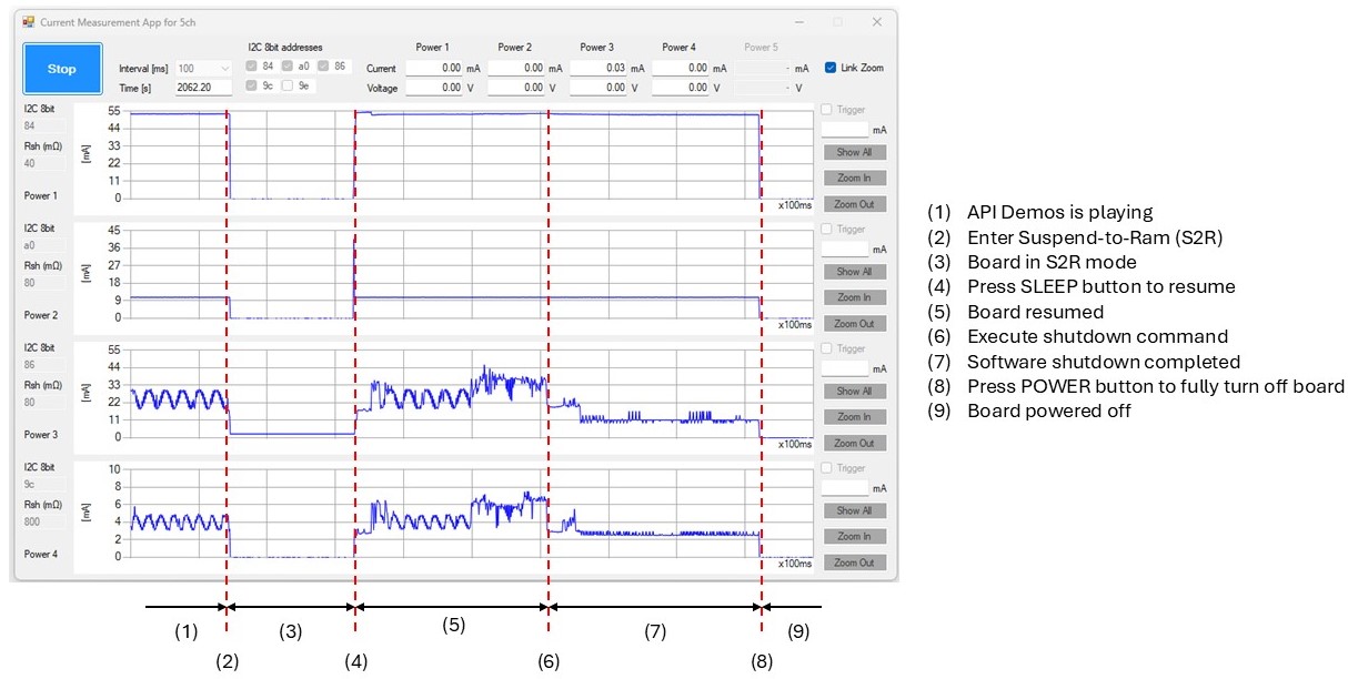
Figure. Voltage and current consumption in S2R mode
Shutdown device
Shutdown the device as shown:
Method 1: Shutdown via board's console
On board's console:
1)
2) Press and Hold the Power button (POWER) for 2 seconds to power off the SMARC RZ/G3L after the display shows no signal
Method 2: Shutdown via adb
On Ubuntu Host PC
1)
2) Press and Hold the Power button (POWER) for 2 seconds to power off the SMARC RZ/G3L after the display shows no signal
Method 3: Shutdown via Android GUI
On Android GUI
From top center of the screen, swipe down. When the screen shown below is displayed, tap the power icon at the bottom center of the screen, then tap Power off.
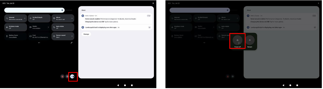
Once the "shutting down" message disappears.
Press and Hold the Power button (POWER) for 2 seconds to power off the SMARC RZ/G3L.